-Rember to earth the power line.
-Ascertain the absence of power in pre-existent gates and remove any manual lock.
-Before the first functioning ascertain that the automation has been carried out according to
the law in force.
6
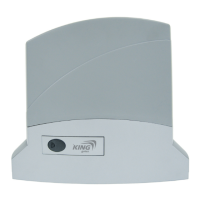
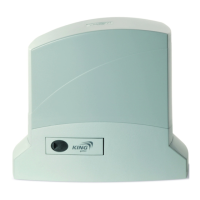
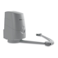
TECHNICAL DATA
Code D 500 D 1000 D 24/400 D 24/600 D 24/1000
Power supply
(Vac 50 Hz)
230
Motor
(Vac/Vdc)
230 24
Motor power
(W)
200 400 40 70 80
Speed
(m/min.)
10 9 ÷ 15
Overload cut-out
(°C)
140
-
Weight
(kg)
10 12 9 11
Max weight of the gate
(kg)
500 1000 400 600 1000
Cycle of work
(%)
30 50 80
Dimensions
(mm)
325x185x274
Working temperature
(°C)
-20 ÷ +55
Read the instructions with care before installing the product.
The producer disclains all responsibility for any damage or bad functioning caused by
non-osservance of the instructions or bad connection that may result in poor safety and
functioning of the gear-motor.
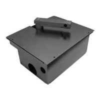
Tighten the two foundation tie-beans on the plate with the two M10 nuts (pic.2)
In accordance with the size, fix the plate on a concrete base of adeguate dimension,
complying with fixing distances which have to be vertical and parallel to the gate.
Arrange one or more sheaths for electric cables (pic.3).
Once the base has hardened, loose the nuts, place the gear-motor on the foundation plate
ascertaining it is parallel to the gate, and gently tighten the two nuts provided (pic.4).
PLATE FIXING
INSTALLATION
Set the gear-motor on manual functioning (pic.10).
Wide open the gate’s door.
Place the rack, place the first element on the pinion and fix it with M6 screws to the gate
(pic.5) Move the door manually and repeat the procedure with the other elements using a
distance spacer to ensure the correct position from the rack (pic.6). It is advisable to leave
2mm between the rack the gear to avoid the gate resting on the gear-motor (pic.7).
For the final height adjustment between the motor and the rack, use the 4 screws located
on the external sides for a height up to 15mm (pic.8).
The final fixing of the gear-motor is done by tightening the 2 nuts placed on the
foundation tie/beans.
RACK FIXING
FINAL ADJUSTMENT
GB