Do you have a question about the King gates Book and is the answer not in the manual?
General safety instructions and warnings before installing the product.
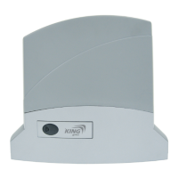
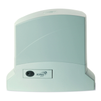
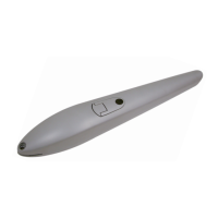
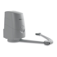
Details available versions of the motor and rails, including technical specifications.
Technical specifications for Book 550 and Book 1000 Led models.
Diagram of a typical system with labeled components and connections.
Detailed dimensions of the gate automation system, including useful run.
Table showing effective run based on distance 'H' and used hole 'F'.
Instructions for assembling rails, with a note to skip if rail is pre-assembled.
Step-by-step guide for assembling the GRB23 or GRB4 guide rails.
Procedure for fixing the bracket to the carriage for GRB3, GRB23, and GRB4 models.
Instructions on how to tension the belt correctly for proper automation function.
Steps to fix the gear motor to the guide, considering different positions.
Guide on fixing the rail to the ceiling or directly to the ceiling structure.
Procedure to fix the automation bracket to the door securely.
How to adjust the end-of-stroke points for the gate's opening and closing.
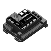
Steps to start the control unit system for sectional door automation.
Default operating modes of the control unit with standard programming.
Recommended cable sections and wiring guidelines for the control unit.
Important notes and rules for connecting devices to the control unit terminals.
Detailed wiring diagram for connecting power, motor, and accessories to the control unit.
Procedure to program the transmitter for the main gate opening/closing function.
How to program a transmitter button for the courtesy light function.
Procedure to program a transmitter button for pedestrian (partial) opening.
Method to delete all previously programmed radio remote controls from the memory.
Explanation of DIP switch settings and their corresponding functions.
Description of FORZA (power/speed) and OBS (obstacle sensitivity) trimmer adjustments.
Operation mode where motor runs only when START/RAD button is held.
Mode with automatic closing after a set pause time.
Mode where each command triggers the next step (open, stop, close).
Mode with step-by-step operation and automatic closing enabled.
Important warnings and notes regarding the travel programming procedure.
Procedure to set the manoeuvre time and motor force for the gate.
Advanced procedure to set the beginning point of slowdowns in opening and closing.
Procedure to set the pause time before automatic closing occurs.
Procedure to set the pedestrian opening for sliding garage doors.
Explanation of the FORZA trimmer for adjusting motor power and speed.
Explanation of the OBS trimmer for obstacle detection sensitivity and delay.
Meaning and function of the yellow SET LED on the control unit.
Meaning and function of the red RAD LED on the control unit.
Indicates errors in encoder reading when both LEDs are on.
How to connect external start commands (e.g., key selectors) to the control unit.
How to connect external stop commands (emergency stop buttons) to the control unit.
How closing safety devices (photocells) operate based on DIP1 setting.
How obstacle detection works via power absorption and OBS trimmer.
How to connect and use a flashing lamp with the automation system.
How to connect an external antenna to improve radio signal range.
Solutions for common problems like failure to start, partial cycles, and radio issues.
Explanation of symbols used in 'MEMO PROG' for programming.
Manual operation without external release, requires external lock.
Manual operation with automatic reconnection of carriages.
Procedure to replace the courtesy light lamp.
Contact information and details for the producer, King Gates S.r.l.
| Brand | King gates |
|---|---|
| Model | Book |
| Category | Gate Opener |
| Language | English |