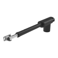
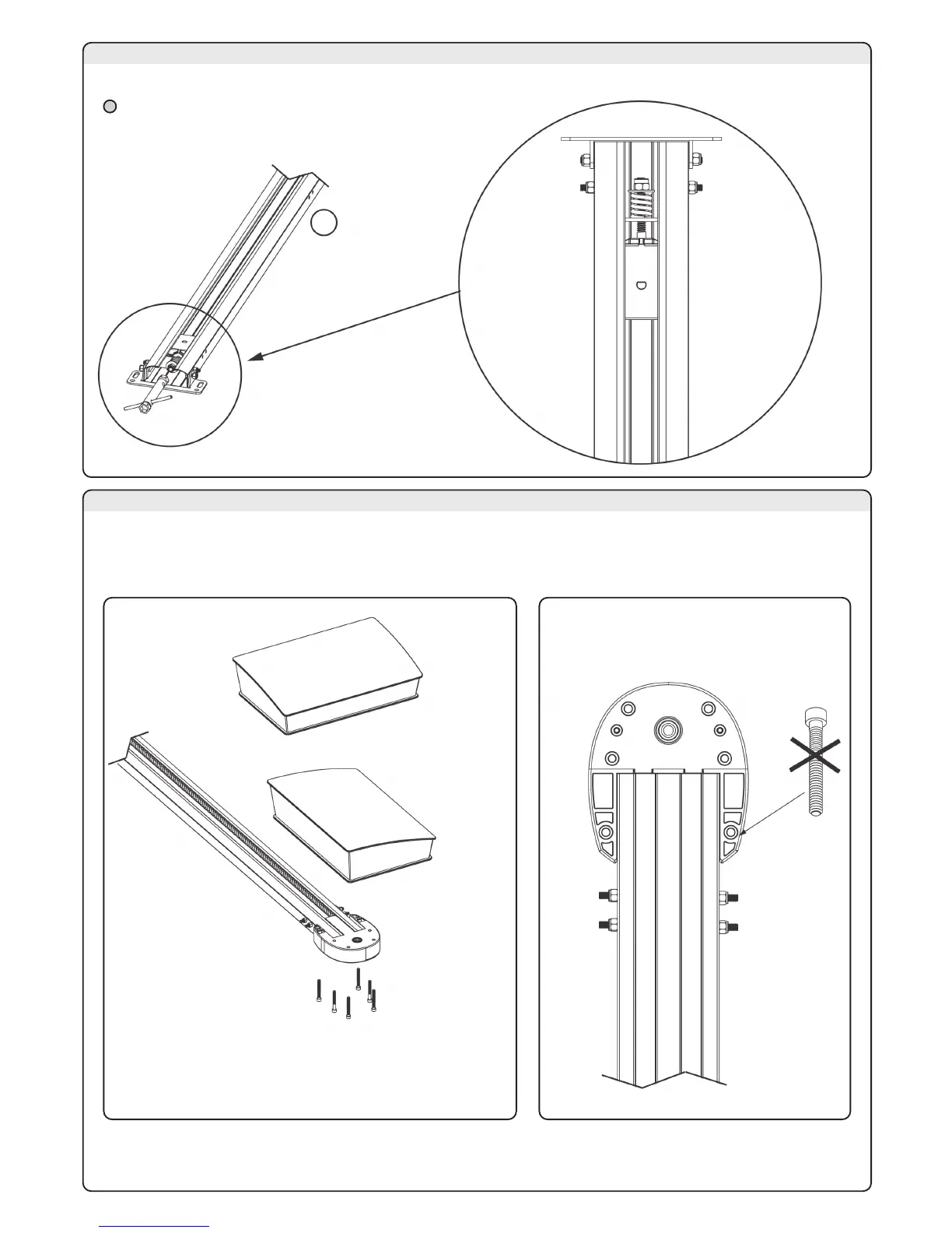
1 - Tension the belt screwing the M8 nut until the complete compression of the spring (fig.12 and 13).
1- Put the carriage in the middle of the rail (see picture 10 and 11)
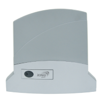
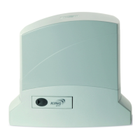
2 - Choose the side of the motor and fix it to the support (fig.14).
3 - If the motor is fixed in position 1 screw the 6 screws 6.3mm x 50
If the motor is fixed in position 2 don’t screw the screw in picture 15
3D - BELT TENSIONING
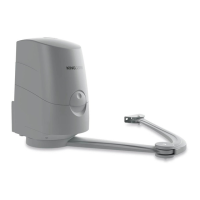
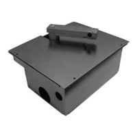
3E - FIXING THE GEAR MOTOR TO THE GUIDE
1 - Considering the installation limits (paragraph 2) and the chart in picture 18 fix it above the door, centrally to the door
and with the bracket “O” perfectly level (fig.16).
Where the installation site allows, the possibility exists to fix the guide directly onto the ceiling,
turning the bracket (fig.17).
2 - Unscrew the M6 nut (P) and anchor the fastening brackets to the ceiling above the guide verifying they are perpendicular
to the profile (fig.20). For the choice of the holes, see the chart in picture 18
3F - FIXING THE RAIL
#EILINGHEIGHT(
F)G
0 cm
4 cm
8 cm
12 cm
16 cm
20 cm
24 cm
28 cm
32 cm
36 cm
40 cm
"RACKET
HOLE
1
2
3
4
5
6
7
8
9
10
11
1
2
3
4
5
6
7
8
9
10
11
Position 1
Position 2
(
(
If the belt is tensioned after the door installation, the automation
must be set on manual functioning