- Verify the presence of voltage in the terminals of the external fuse box
- Verify the fuse
- STOP contact open: check for possible STOP commands connected. If absent, jumper the input
17 - INCONVENIENTS AND REMEDIES
THE AUTOMATION DOESN’T START
- The photocell is obstructed: check the correct positioning of the photocells and their range
-The photocell is absent: if there are no devices connected jumper the input
-A normally closed contact, or a defective contact, is connected on “STAR” input
THE AUTOMATION PERFORMS ONLY THE OPENING CYCLE
- The radio transmitter hasn’t been correctly programmed
- The battery of the transmitter are exhaust. Change them
THE AUTOMATION WORKS ONLY BY WIRE
- Too low obstacle sensitivity. Increase the “OBS” trimmer
- Intervention of safety devices. If there are two pairs of photocells, they could see each other.
Invert a receiver with its transmitter
THE AUTOMATION STARTS BUT, AT A CERTAIN POINT, IT INVERT THE TRAVEL
- Not enough power. Set “FORZA” trimmer at maximum level, and program the automation again.
- Perform a professional programming procedure and reduce at minimum (or remove) the slowdowns.
THE AUTOMATION STARTS BUT, AT A CERTAIN POINT, IT STOPS
- Perform a programming procedure. Then try again
WHEN THE BOARD IS POWERED UP, BOTH THE LED ARE ON
- Tighten the belt when the automation is unlocked (see Section 3C)
THE BELT OUT THE SLIDING GUIDE
18 - MEANING OF THE SYMBOLS OF “MEMO PROG”
MEANING OF THE SYMBOLS
led SET
led SET
led SET
SET
1 s
SET
2 s
RAD
1 s
4HEYELLOW,%$3%4
BLINKS
$OORONTHEMIDDLE
OFTHETOTALRUN
4HEDOOROPENS
PARTIALLY
4HEDOORISFULL
OPENED
4HEDOORISFULL
CLOSED
3ETTHESUITABLE
STARTFORTHESLOWING
INOPENING
3ETTHESUITABLE
STARTFORTHESLOWING
INCLOSING
4HEYELLOW,%$3%4
LIGHTSUP
4HEYELLOW,%$3%4
ISSWITCHEDOFF
led RAD
led RAD
led RAD
10s
=
1
4HERED,%$2!$
BLINKS
4HERED,%$2!$
LIGHTSUP
4HERED,%$2!$
ISSWITCHEDOFF
%ACHBLINK
MEANS
SOFPAUSE
0RESSBUTTON3%4
FORSECOND
0RESSBUTTON3%4
FORSECONDS
0RESSBUTTON2!$
FORSECOND
RAD
3 s
0RESSBUTTON2!$
FORSECONDS
START
1 s
0RESSBUTTON34!24
FORSECOND
-AKEATRANSMISSION
PRESSINGTHEDESIRED
BUTTONONTHE
TRANSMITTER
3ETTHESUITABLEWIDTH
FORTHEPEDESTRIANOPENING
PARTIALOPENENIG
Mode 1
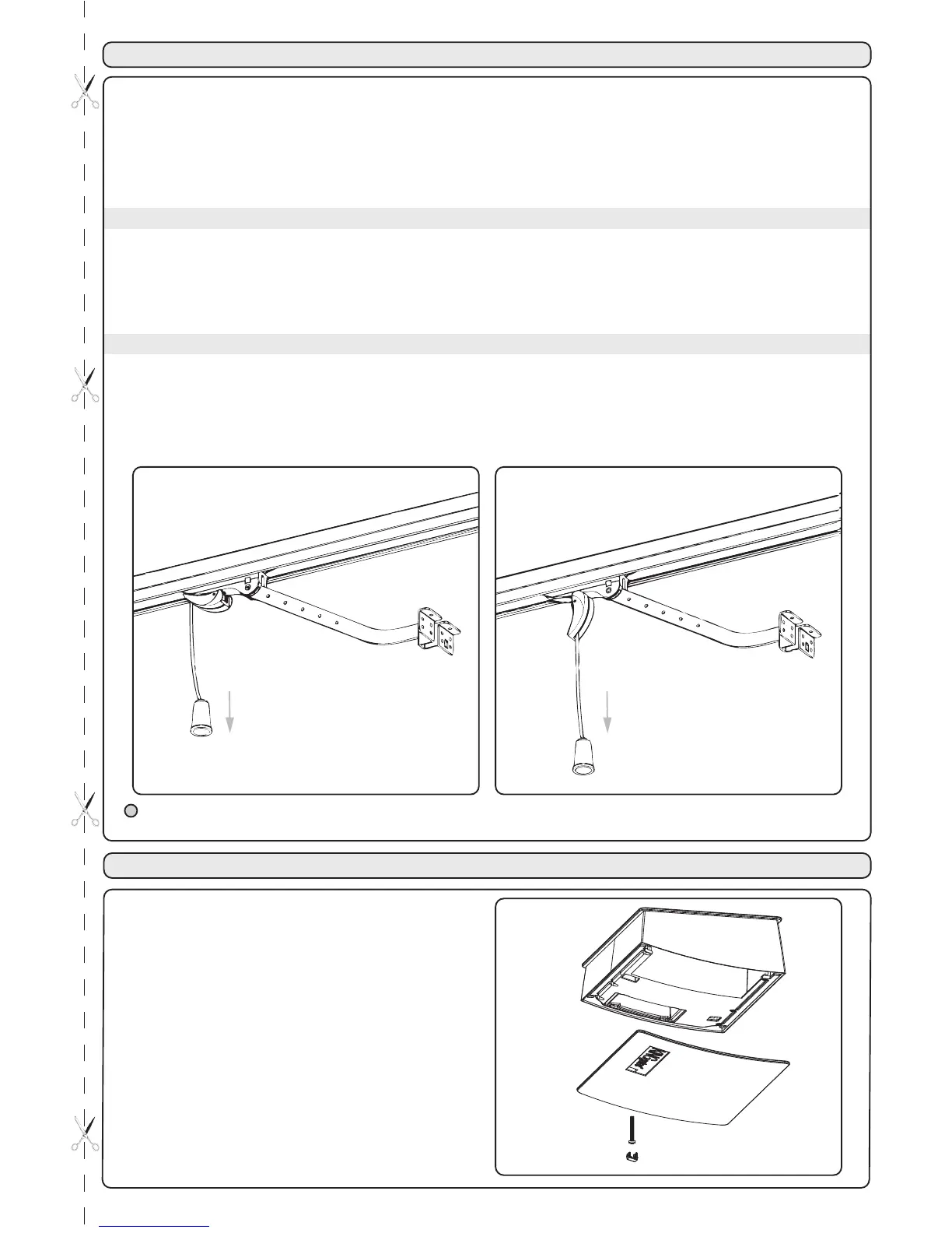
The release manoeuvre has been provided for manual opening of the door in case of a power cut or motor breakdown.In
order to enable all types of use (for example the presence of an electric or outside lock) the handle has been designed to
lock itself perpendicularly to the carriage, allowing the user to completely do away with door automation.
The gear motor can also be released from the outside installing the optional accessory “SBLO01“ (external unlocking
system to be applied on handle lock) o “SBLO 500” (external unlocking system to be applied with an hole in
the door).
The two manual operating modes are:
The user that exits from the garage can close the gate and re-enter without having to repeat the release operation. The
automation release must be guaranteed by an external blocking system (a lock, for example).
INSTRUCTIONS:
- Pull the release cord downwards as illustrated in figure 1 until the handle perpendicular to the guide is blocked,
unhooking the lower driving carriage.
- Move the gate manually
Mode 2
The user that exits the garage, making use of the reconnection of the automation during the manual closing operation, obtains
the recoupling of the carriages and thus the blocking of the gate.
INSTRUCTIONS:
- Pull the release cord downwards as illustrated in figure 1 until the handle perpendicular to the guide is blocked
- Move the door manually
- Return the handle to the original position (figure 2)
MANUAL MANOEUVRE
- Open the cover as shown in Figure 3
- Remove the lamp is not working and insert a
new 24V 15W max the same size
COURTESY LIGHT REPLACEMENT
During manual operation use only the door for opening and closing, thus avoiding strain on the carriage
by pulling the release cord.