1 - Unscrew the M6 screws and the M6 nuts
2 - Insert the arm and the bracket and fix them (fig.9)
3C - FIXING THE BRACKET TO THE CARRIAGE ON “GRB3”, “GRB23” AND “GRB4”
'2"'2"'2"
3 - INSTALLATION
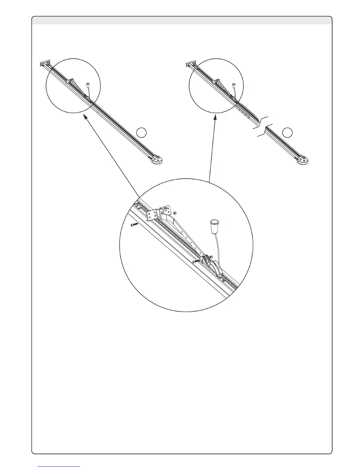
3B - ASSEMBLING THE GUIDE “GRB23” (1.5m X 2) OR “GRB4” (3m+1m)
1 - Prepare the two profiles and the joint and fasten them by the four screws (detail 2)
2 - Insert the fastenings for the brakets (details 3 and 4)
In order to assemble the rails, proceed as shown in the following paragraphs.
If the rail is “GRB3” (3X1m) skip the paragraph 3A because the rail is preassembled.
3 - Extend the belt and check that the unit is lined up, with the teeth facing inwards, then insert the downward side
of the carriage (fig.6).
4 - Insert the “belt unit” into the guide, from the screw end until the motor support is restrained (fig.7).
5 - Insert the screw M8x70 into the bracket. Insert in this order the spring, the washer and the self-locking M8 nut (fig.8).
3A - INTRODUCTION