SVC
P
123
456
789
*0#
P
1
P
2
P
3
P
4
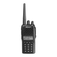
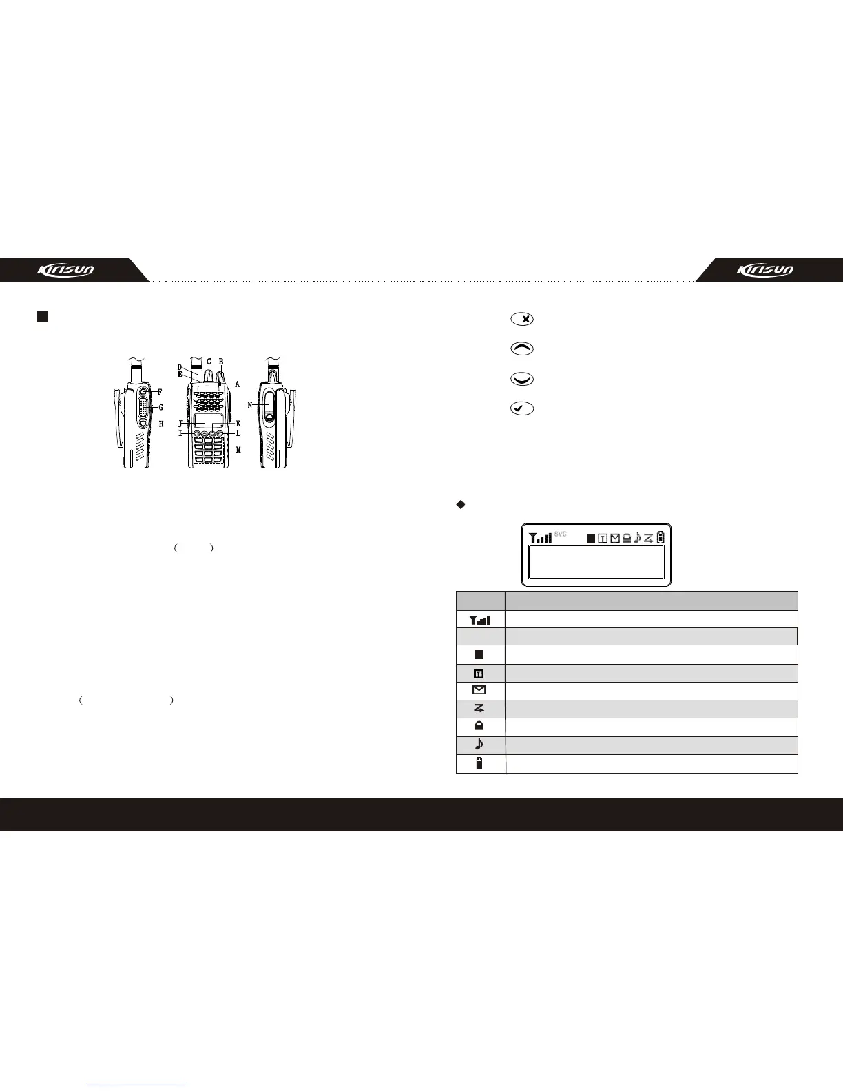
The functions of the components are as follows:
A. LED Indicator
Lights red while transmitting;
Lights green while receiving.
B. Power/Volume Switch Knob
Turn clockwise till a click is heard to switch on the radio.
Turn counterclockwise till a click is heard to switch off the radio.
Rotate to adjust the volume after turning on the radio.
C. Channel Selector
Rotate to select the channel 1-128.
D. Antenna
E. Top Button (programmable button)
It is recommended to be set as the emergency warning Button.
F. Side button 1 (programmable button)
G. PTT PUSH-TO-TALK :
To make a call, press and hold the PTT button, then speak into the
microphone with normal voice. Release the PTT button to receive
signals.
H. Side button 2 (programmable button)
RADIO OVERVIEW
I. Button
Return and delete button in the menu.
J. Button
Select Button.
K. Button
Select Button.
L. Button
Enter and Confirm Button.
M. Numeric keypad
N. Microphone/speaker jacks
For connecting microphone/speaker.
P
1
P
2
P
3
P
4
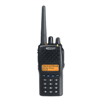
Explanation for the screen
Description
Signal intensity
SVC
Compandor
Disturbance Frequency
Busy channel lockout
Scanning
Key lockout
Signal reminder is programmed
Battery capacity, flashes when the battery power goes too low
P
Icon
5
6
 Loading...