2.9 LUBRICATION DIAGRAM
The lubrication of the compressor is of the forced feed
type and effected by a gear pump driven from the
crankshaft. The oil circuit is shown in Fig. 5 & 6.
The oil enters the pump via the wire gauze suction oil
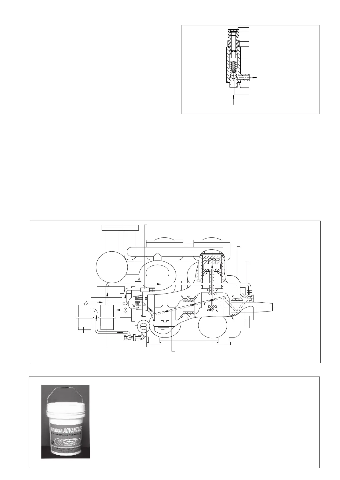
strainer. High pressure oil is fed to the differential
pressure regulator where the oil pressure is reduced and
is fed to shaft seal housing, via the paper type delivery
oil strainer, Oil reaches all main bearings, big end and
small end bearings via the internal ways in the
crankshaft and connecting rods. The thrust bearing of
the crankcase is lubricated via a separate oil way in the
bearing cover. Lubrication of the cylinder liners is
effected by surplus oil from the gudgeon pins and the big
ends. The arrows indicate the direction in which the oil
flows. Excess of the oil is led back, via a hole in
crankshaft to the oil pump housing from where to
externally fitted oil pressure regulator.
From the oil pressure regulator the oil is returned into
the crankcase behind the oil level glass, to complete the
lubrication circuit. A pressure gauge is connected to the
oil return line on oil pump before the oil pressure
regulator through a three way stop valve. To stop the
electric motor at the time of too low of oil pressure, one
oil pressure differential pressostat may be connected to
this 3-way stop valve. The oil pressure should be adjust-
ed by means of the oil pressure regulator & should be at
2
least 1.5 kg/cm higher than the crankcase pressure.
Figure 5 : Oil Pressure Regulator
The oil level and the oil return jet are visible through the
two level glasses, which are fitted at same level but in
opposite walls of the crankcase. The oil level should
always be visible in the oil level glass whilst it is not
advisable to let it rise above its centre line. For correct
lubricant to be used, refer lubricating chart.
2.10 PRESSURE EQUALIZING LINE
A pressure equalizing line is fitted between the suction
strainer housing and the crankcase. This line provides an
open connection between the crankcase and the suction
line, which is necessary for evacuating the gas from
crankcase before topping up the oil. It also prevents
pressure build up due to gas blow-by past the pistons.
Recommended Oil
KIRLOSKAR ADVANTAGE AC & REFRIGERATION COMPRESSOR OIL
n 20 ltr smart pack
n Easy to buy, stock and use
n No risk of loose purchased adulterated and reconditioned oil
n No need to invest on 200 ltr drum
n Grade ISOVG68
n Suitable for refrigerants NH3 and R22
n Evaporating temp. range: +10ºC to -25°C
Figure 6 : Lubrication System
LUBRICATING OIL PRESSURE REGUALTOR
OIL WAY TO
THRUST BEARING
EXTERNAL OIL
DISCHARGE
LINE
SHAFT SEAL
HOUSING
OIL CHANNEL IN CRANKSHAFTSIGHT GLASS
OIL DISCHARGE FILTER
OIL SUCTION
FILTER
OIL PUMP
EXTERNAL OIL
RETURN LINE
CAP
PACKING
NIPPLE
PACKING
O RING
SET PIN
TO OIL
LEVEL GLASS
VALVE HOUSING
BALL VALVE
7