8. ACCESSORIES:
8.1 PRESSURE SWITCHES
These pressure switches are provided for safety of
compressor and plant operation. It is advisable not to bypass
using of pressure switches. Also check, inspect and replace
faulty pressure switches time to time.
These pressure switches are to be used in the delivery line,
suction line and in lubrication line. These pressure switches
are known as pressostats. These pressure switches require to
connect into the electrical control circuit of the compressor
driving prime mover. It may be electric motor or diesel
engine. The function of these pressure switches is to interrupt
the control circuit when abnormal working condition occur.
For detail control circuit wiring diagrams refer following
figures:
Figure 26, 26A and 27 for electrical motor control circuit.
Figure 27A for diesel engine control circuit.
Note: For diesel engine these pressure switches are to be
connected in to the safety control circuit provided on diesel
engine. Hence while using diesel engine as a prime mover
ensure that engine is provided with engine stop solenoid valve
(fuel solenoid valve) having engine safety controls like low
lube oil pressure, over speed control, high water temperature
etc.
8.2 HIGH PRESSURE PRESSOSTAT
This pressostat serves as a protection against excessive
pressure and is connected to the gas delivery line. The
compressor is automatically switched off when the delivery
pressure exceeds the present maximum value. The pressostat
can also be arranged to operate, via an auxiliary contact. an
alarm or a hooter. A lockdevice provides protection against
automatic reclosing of the broken contact when the pressure
falls below the present maximum value. Moreover, to restart
the compressor, the lock device has to be first reset manually.
Note: Before restarting the compressor the reason for the
stoppage should be traced and rectified.
8.3 LOW PRESSURE PRESSOSTAT
This pressostat is connected in the gas suction line and is
adjusted at a minimum suction pressure, Its operation and
locking off are similar to those of the H.P. pressostat. A fall in
the suction pressure below the preset minimum pressure
causes the electric motor to be switched off.
8.4 OIL PRESSURE DIFFERENTIAL PRESSOSTAT
This pressostat serves as a protection against too low oil
pressure and is installed between the oil pressure gauge stop
valve and the suction pressure gauge stop valve (on two-stage
compressors the crank case pressure gauge stop valve). Thus
the device is acted on by the actual pressure differential across
the pump, as indicated by these gauges. The minimum safe
true oil pressure is present on the pressostat, When the true oil
pressure drops below the preset valve, the electric motor is cut
out by interruption of the electrical control circuit. This circuit
is automatically remade when the pressure exceeds the preset
valve. Pressostat to be manually pre-set. The oil pressure
switch incorporates an automatic time delay to bridge the
main contacts during start-up to enable the compressor to start
initially before any oil pressure has been built up. If an
alternative type of oil pressure switch without automatic time
delay is to be used then external time switch is necessary
during start-up.
8.5 COMBINED HP/LP PRESSOSTAT
This is a single pressostat, combination of high pressure and
low pressure pressostat. This pressostat has fixed high
2
pressure trip setting of 21.0 kg/cm g. Note that it has no
differential pressure setting to HP side. It is to be manually re-
set after correcting the HP fault. So far LP side is concern, it
has two settings, a) Min LP trip set pressure b) Differential re-
start pressure.
HP/LP and LP/OP pressostat with by-pass toggle switch
electrical connections are shown in figure 27.
8.6 PRESSURE GAUGE PANEL
The no. of pressure gauges in panel depends upon type of
compressor, i.e. 3 nos. for single stage compressor and 4 nos.
for two stage compressor. It is advisable to install the gauge
panel at readable height and about 1 meter away from the
compressor. This will protect the gauges and the piping from
vibrations of the compressor. Figure given below illustrates
mounting of the gauge cut-out panel.
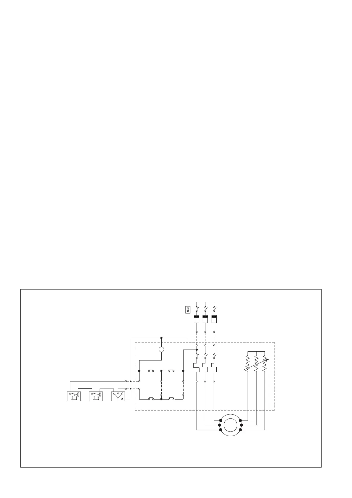
Figure 26: Schematic Wiring Diagram for Slip Ring
Motors with Stator Rotor Starters.
3 Ø 50 HZ 415 V SUPPLY
M L1 L2 L3
SWITCH
FUSE
ROTOR RESISTANCE
STATOR
CONTROL
OVERLOAD
RELAY
MANUAL
STATOR
ROTOR
STARTER
3 Ø SUPRING MOTOR
FULL RESISTANCE
ON
FULL RESISTANCE
OFF
P.B.
M
230 V
M.V. COIL
MP 1
LOW
SUCTION
PRESSURE
CUTOUT
MP 5
LOW
SUCTION
PRESSURE
CUTOUT
MP 55
LOW
SUCTION
PRESSURE
CUTOUT
(ALL DANFOSS MAKE SHOWN)
220
LM
1
3
23
1
2
26