4-7
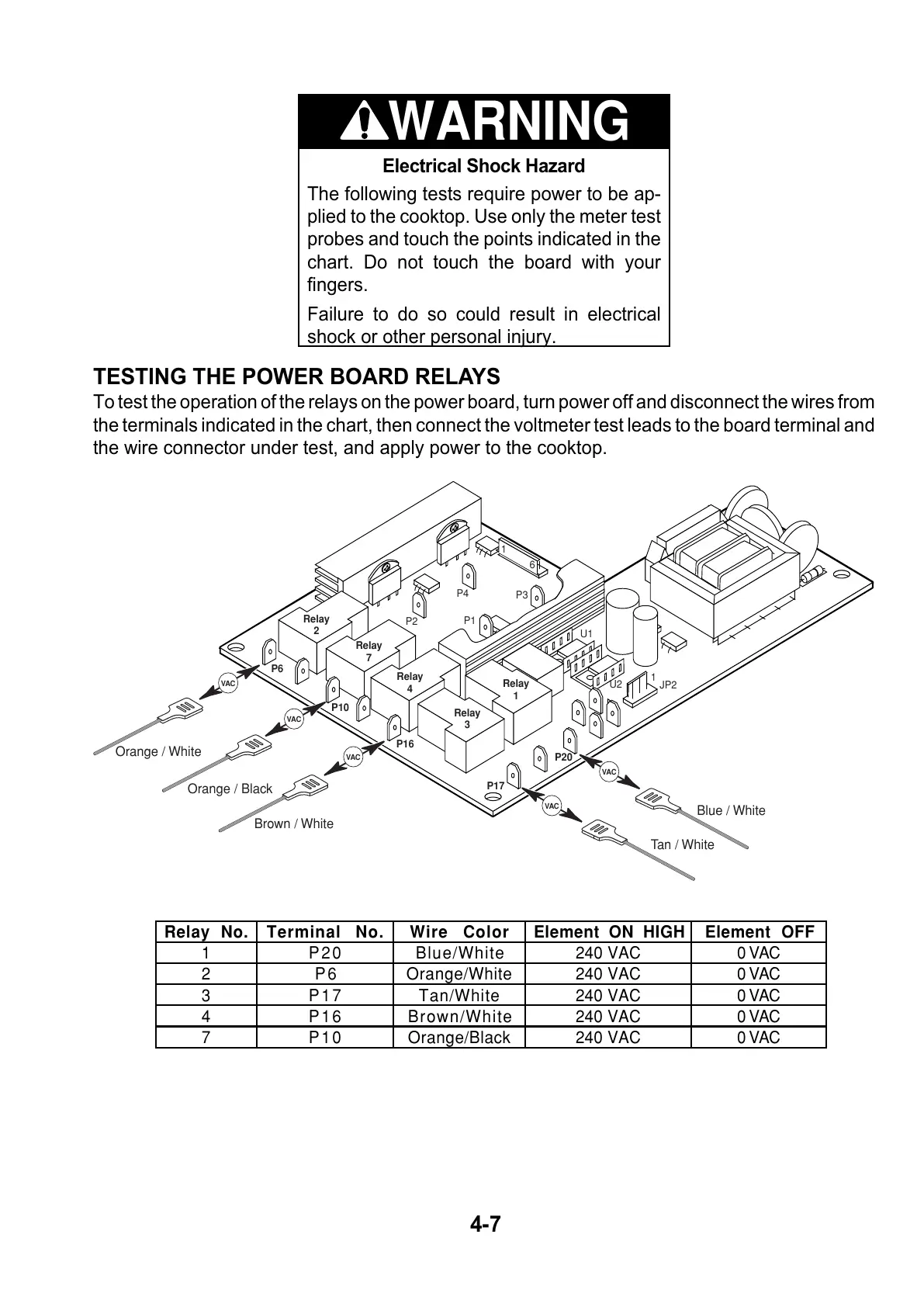
TESTING THE POWER BOARD RELAYS
To test the operation of the relays on the power board, turn power off and disconnect the wires from
the terminals indicated in the chart, then connect the voltmeter test leads to the board terminal and
the wire connector under test, and apply power to the cooktop.
U1
U2
P20
P17
P16
P2
P4
P3
P1
P10
P6
6
1
1
JP2
Relay
2
Relay
7
Relay
4
Relay
3
Relay
1
Blue / White
Tan / White
Brown / White
Orange / Black
Orange / White
VAC
VAC
VAC
VAC
VAC
Electrical Shock Hazard
The following tests require power to be ap-
plied to the cooktop. Use only the meter test
probes and touch the points indicated in the
chart. Do not touch the board with your
fingers.
Failure to do so could result in electrical
shock or other personal injury.
WARNING
Relay No. Terminal No. Wire Color Element ON HIGH Element OFF
1 P20 Blue/White 240 VAC 0 VAC
2 P6 Orange/White 240 VAC 0 VAC
3 P17 Tan/White 240 VAC 0 VAC
4 P16 Brown/White 240 VAC 0 VAC
7 P10 Orange/Black 240 VAC 0 VAC