Document No.:KE-4011-03 Page: 8/27
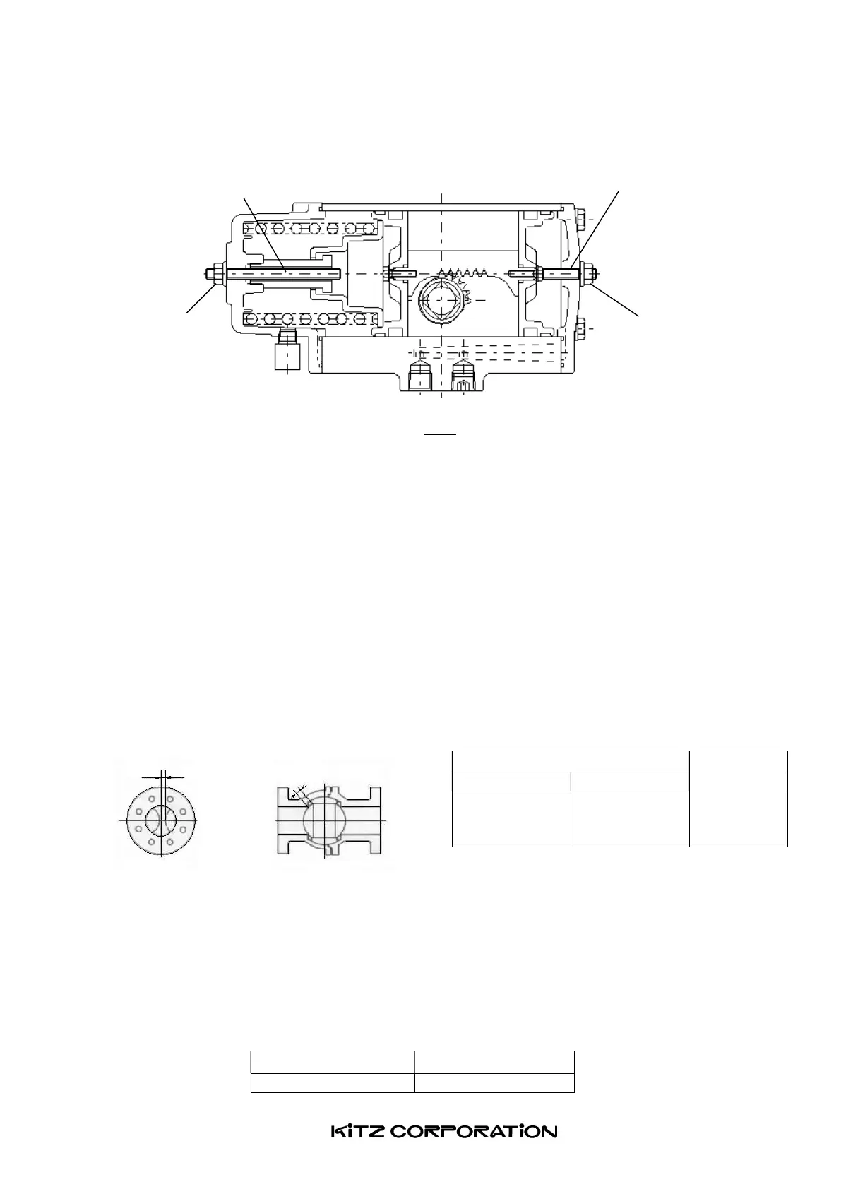
14. Adjusting Valve Opening Range
Fig 4
14.1 Release the compressed air from the actuator housing. Loosen a hexagon nut and adjust the
position of either one of two stopper bolts illustrated above for your desired valve opening position.
The dimensional requirements of ball valve balls ([L] in Table 3) must be satisfied. Refer to Table 4
on the sizes of stopper bolts.
14.2 Clockwise rotation of the stopper bolt makes the valve operation range smaller, and counter-
clockwise rotation makes it larger.
14.3 After having tightened the nuts, supply the compressed air to the port and check the valve opening
range. Repeat this work until you have a satisfactory result
Table 3: Adjustment for KITZ Class 150/300 full-bored floating ball valves (*5)
(*5) In the case of 3-way ball valves, adjust the center of the ball bore so that it may align with the
center of the valve end flange bore. During adjustment, you can monitor the work through either side
opening of the valve end flanges.
Table 4: Size of stopper bolts (Hexagon socket set screws)
Actuator type
Bolt size
FBS-1 M6
Valve size (full-bore)
L[mm]
NPS DN
3/8~ 3/4
1~11/2
2
10~ 20
25~40
50
5.0
5.5
6.0
Open side stopper bolt
Closed side stopper bolt
Nut
Nut
Fully closed
fully closed position
L L