l abc
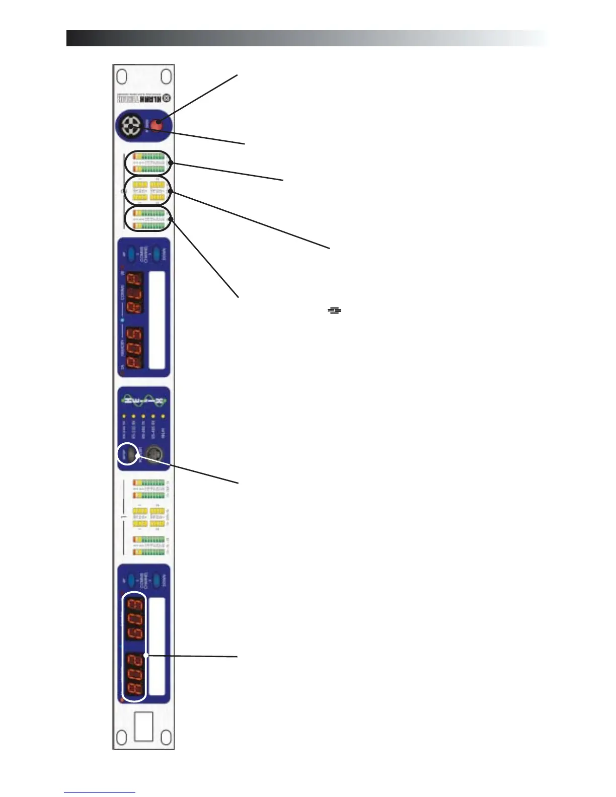
Identification of controls:DN9344
Power switch
Power on indicator
Section 2 input metering
incorporating multi-point clip
indication. This meter indicates the
level immediately after the input gain
trim.
Section 2 output metering
incorporating multi-point clip
indication. This meter indicates the
actual output level from the unit, while
the red clip light indicates internal
clipping, which is monitored at every
internal processing stage.
Section 2 dynamic EQ
metering. Four separate meters are
provided, to allow continuous
monitoring of all dynamic EQ
sections.
SETUP key. Press and hold to enter
SETUP menu. The setup menu is used to
select communications channel (address)
for remote control, and to enable contact
closure operation. Note that each DN9344
has TWO independent communications
channels (one for Section 1 and one for
Section 2) as it contains the equivalent of
TWO DN9340 master units. The
Communications Mode display will flash,
indicating that it can be changed using the
UP and DOWN keys. A momentary press
of the SETUP key will toggle between the
display of the electronic scribble-strips and
display of Last Memory Recalled and the
Communications Mode (which will not
flash indicating that it cannot be changed).
The large red alphanumeric displays can be
used to show electronic scribble-strip
information, Last Memory Recalled, and
Communications Mode. In remote control
mode, the displays show a 3-character
name for each audio channel. This name is
set from the master unit. In relay (contact
closure) mode or stand-alone mode the
displays show Last Recalled Memory and
Communications Mode.
T-DEQ
37
 Loading...