4 5
OTHER MEASUREMENT APPLICATIONS
Maximum Input: 600V DC or 600V AC RMS
• Diode Test: Approx. 1mA, open circuit voltage ~3.0V DC
• Continuity Check: Audible signal <10Ω, max current 1.5mA
• Sampling Frequency: 3 samples per second
• Auto Power off: After ~15 minutes of inactivity.
• Overload: "OL" indicated on display
• Polarity: "-" on display indicates negative polarity
• Display: 3-3/4 digit, 4000 Count LCD
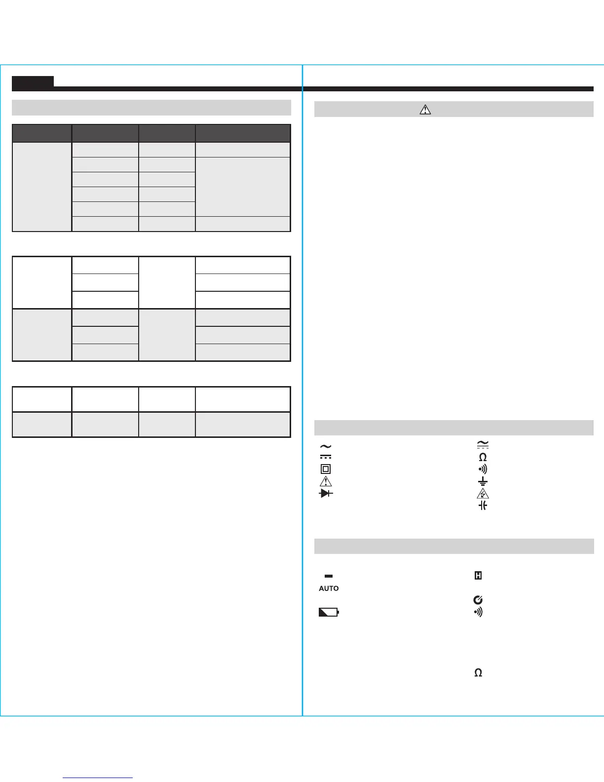
ELECTRICAL SPECIFICATIONS
Function Range Resolution Accuracy
Capacitance
40.00nF 0.010nF ±(4% + 25 digits)
400.0nF 0.100nF
±(4% + 8 digits)
4.000μF 0.001μF
40.00μF 0.010μF
400.0μF 0.100μF
4.000mF 0.001mF ±(10% + 9 digits)
Maximum Input: 600V AC RMS or 600V DC
Temperature
°F
-40°F to 104°F
1
°F
±(2.0% + 8 digits)
105°F to 932°F
±(1.6% + 5 digits)
933°F to 1832°F
±(2.0% + 4 digits)
Temperature
°C
-40°C to 40°C
1
°C
±(2.0% + 4 digits)
41°C to 500°C
±(1.5% + 3 digits)
501°C to 1000°C
±(1.5% + 2 digits)
Maximum Input: 600V AC RMS or 600V DC
Frequency
10Hz to
1MHz
0.001Hz
to 1kHz
±(0.1% + 5 digits)
Duty Cycle
0.1% to 99.9%
(≤100kHz)
0.01%
±1.5%
(Range: 10% – 90%)
Maximum Input: 600V AC RMS or 600V DC
ENGLISH
WARNINGS
To ensure safe operation and service of the meter, follow these
instructions. Failure to observe these warnings can result in
severe injury or death.
• Before each use verify meter operation by measuring a known
voltage or current.
• Never use the meter on a circuit with voltages that exceed the
category based rating of this meter.
• Do not use the meter during electrical storms or in wet weather.
• Do not use the meter or test leads if they appear to be damaged.
• Use only with CAT III or CAT IV rated test leads.
• Ensure meter leads are fully seated, and keep fingers away from
the metal probe contacts when making measurements.
• Use caution when working with voltages above 25V AC RMS or
60V DC. Such voltages pose a shock hazard.
• To avoid false readings that can lead to electrical shock, replace
batteries when a low battery indicator appears.
• Do not attempt to measure resistance or continuity on a live circuit.
• Always adhere to local and national safety codes. Use personal
protective equipment to prevent shock and arc blast injury where
hazardous live conductors are exposed.
• To avoid risk of electric shock, disconnect leads from any voltage
source before removing battery door.
• To avoid risk of electric shock, do not operate meter while battery
door is removed.
SYMBOLS ON METER
AC (Alternating Current)
AC/DC Current
DC (Direct Current) Resistance (in Ohms)
Double Insulated Class II Audible Continuity
Warning or Caution Ground
Diode Risk of Electrical Shock
Hz
Frequency Capacitance
%
Duty-cycle V Voltage (Volts)
°
F/
°
C
Temperature (Fahrenheit / Celsius) A Amperage (Amps)
SYMBOLS ON LCD
AC AC (Alternating Current) DC DC (Direct Current)
Negative Reading Data Hold
Auto Ranging MAX Maximum Value Hold
MIN Minimum Value Hold Auto Power Off
Low Battery Audible Continuity
°
F
Degrees (Fahrenheit)
°
C
Degrees (Celsius)
M
Mega (value x 10
6
)
k
kilo (value x 10
3
)
m
milli (value x 10
-3
)
μ
micro (value x 10
-6
)
n
nano (value x 10
-9
)
V
Volts
A
Amps Ohms
Hz%
Frequency/Duty Cycle