Do you have a question about the Klein Tools CL900 and is the answer not in the manual?
Details specifications for AC/DC voltage measurements.
Details specifications for AC/DC current measurements.
Details specifications for measuring inrush current.
Details specifications for resistance measurements.
Provides critical safety instructions to prevent severe injury or death.
Guides on setting up and performing an inrush current test.
Details how to use the non-contact voltage tester and its signals.
Explains using CATIII/CATIV shields for safety in specific measurement locations.
Details the procedure for measuring AC and DC current using the clamp.
Explains the steps to measure inrush current, including setup and interpretation.
Guides on measuring AC/DC voltages up to 1000V, including lead connection.
Explains how to perform measurements using the Low Impedance (LoZ) voltage setting.
Details how to perform continuity tests, including setup and results interpretation.
Outlines the procedure for measuring resistance and interpreting readings.
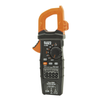
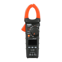
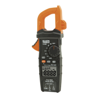
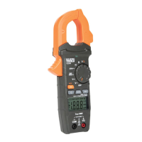
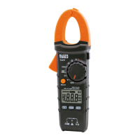
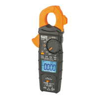
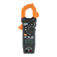
The Klein Tools CL900 is an auto-ranging, true root mean square (TRMS) digital clamp meter designed for comprehensive electrical measurements. It measures AC/DC current via its clamp and AC/DC voltage, resistance, continuity, frequency, duty-cycle, and tests diodes using test leads. The device features a Low Impedance (LoZ) mode to identify and eliminate ghost or stray voltages, and a dedicated mode for capturing Inrush Current.
The CL900 is equipped with a 6000-count LCD display that provides clear readings. Its function selector switch allows users to easily switch between various measurement modes. The clamp is used for non-contact current measurements, while the "COM" and "VΩ" jacks are used for connecting test leads for voltage, resistance, continuity, diode, capacitance, and frequency measurements.
Power On/Off: To power on the meter, rotate the Function Selector switch from the OFF setting to any measurement setting. To power off, rotate the switch back to the OFF setting. The meter automatically powers off after approximately 30 minutes of inactivity to conserve battery life. This auto-power off feature can be deactivated by pressing and holding the "SEL/DC ZERO" button before powering on.
SEL (Select) / DC Zero Button (for Secondary Functions): This button activates secondary functions for various applications. In Current A and Low Impedance modes, it toggles between AC and DC measurements. In Frequency/Duty Cycle Hz% setting, it toggles between these measurements. In Continuity/Resistance/Diode-Test setting, it cycles through these measurements in order. In DC current setting, pressing and holding this button for more than one second initiates the DC ZERO function, which subtracts the measurement present as an offset correction. The default function for each application is printed in white on the meter, while secondary functions are in orange, with an icon on the LCD display indicating the active function.
Data Hold: Pressing the Data Hold / Backlight button holds the current measurement on the display. Pressing it again releases the display to return to live measuring.
Backlight: Press and hold the Data Hold / Backlight button for more than one second to turn on the backlight. The backlight automatically turns off after 3 minutes of inactivity.
Range: The meter defaults to auto-ranging mode (AUTO), which automatically determines the most appropriate measurement range. To manually select a measurement range, press the "RANGE" button. Repeatedly pressing it cycles through available ranges. To return to auto-ranging mode, press and hold the "RANGE" button for more than one second.
MAX/MIN: When the "MAX/MIN" button is pressed, the meter tracks the maximum and minimum values as it continues to take samples. Pressing it toggles between the Maximum (MAX) and Minimum (MIN) values. Holding the button for more than one second returns the meter to normal measuring mode.
Inrush Current: Rotate the Function Selector switch to the Current A setting and press the "INRUSH" button prior to an inrush event. The display will show "----" while waiting for the event. After the inrush event, the current will be captured and displayed. Pressing "INRUSH" again resets the measurement. The inrush measurement period is 100 milliseconds, with a 20-millisecond sampling rate.
Non-Contact Voltage Testing: Press and hold the "NCV" button to test for AC voltage. Approach the conductor with the sensing antenna. The meter provides visual warnings via an LED indicator and audible signals (beeps) when AC voltage is detected. Release the "NCV" button to exit NCV testing mode. Note that only voltages of 90V AC or greater will be detected. It is not recommended to perform continuity and NCV testing simultaneously due to shared audible signals.
AC/DC Current (Less Than 2000A): To measure AC current, press the clamp trigger to open the clamp and place it around a current-carrying wire. Ensure the clamp is completely closed and the wire passes perpendicularly through the center, aligned with the arrow markings. For DC current, press the "SEL/DC ZERO" button to toggle to DC mode. Align the polarity markings on the clamp with the wire's polarity to avoid negative readings. If non-zero values are displayed in DC current mode, an offset correction can be performed by pressing and holding the "SEL/DC ZERO" button for more than one second.
AC/DC Voltage (Less Than 1000V): Insert the RED test lead into the VΩ jack and the BLACK test lead into the COM jack. Rotate the function selector switch to the AC voltage V or DC voltage V setting. Apply test leads to the circuit to measure voltage. If "-" appears on the LCD, the test leads are applied in reverse.
AC/DC LoZ Voltage (Less Than 600V): Insert the RED test lead into the VΩ jack and the BLACK test lead into the COM jack. Rotate the function selector switch to the AC/DC LoZ voltage setting. The meter defaults to AC measurement. Press the "SEL/DC ZERO" button to toggle to DC mode. Apply test leads to the circuit to measure voltage.
Continuity: Insert the RED test lead into the VΩ jack and the BLACK test lead into the COM jack. Rotate the function selector switch to the Continuity/Resistance/Diode-Test setting. Ensure the Continuity Testing icon is visible. Remove power from the circuit. Connect test leads to the conductor or circuit. An audible signal sounds if resistance is less than 50Ω, indicating continuity. If the circuit is open, the display shows "OL".
Resistance Measurements: Insert the RED test lead into the VΩ jack and the BLACK test lead into the COM jack. Rotate the function selector switch to the Continuity/Resistance/Diode-Test setting. Press the "SEL/DC ZERO" button once to enter Resistance testing mode. Remove power from the circuit. Connect test leads to the circuit to measure resistance.
Diode Test: Insert the RED test lead into the VΩ jack and the BLACK test lead into the COM jack. Rotate the function selector switch to the Continuity/Resistance/Diode-Test setting. Press the "SEL/DC ZERO" button twice to enter Diode testing mode. Touch test leads to the diode. A reading of 200-800mV indicates forward bias, "OL" indicates reverse bias or an open device, and approximately 0mV indicates a shorted device.
Frequency/Duty-Cycle: Insert the RED test lead into the VΩ jack and the BLACK test lead into the COM jack. Rotate the function selector switch to the Frequency/Duty-Cycle Hz% setting. The meter defaults to Frequency testing. To test Duty-Cycle, press the "SEL/DC ZERO" button once. Measure by connecting test leads across the circuit.
Capacitance: Insert the RED test lead into the VΩ jack and the BLACK test lead into the COM jack. Rotate the function selector switch to the Capacitance setting. Remove power from the circuit. Measure capacitance by connecting test leads across the capacitor.
Battery Replacement: When the low battery indicator is displayed on the LCD, the batteries must be replaced. Loosen the screw on the battery door, replace the 2 x AAA batteries (observing proper polarity), and then replace the battery door and fasten securely. Always disconnect leads from any voltage source before removing the battery door.
Cleaning: Ensure the meter is turned off and wipe it with a clean, dry, lint-free cloth. Do not use abrasive cleaners or solvents.
Storage: Remove the batteries if the meter will not be used for a prolonged period. Avoid exposing the meter to high temperatures or humidity. After storage in extreme conditions, allow the meter to return to normal operating conditions before use.
Disposal/Recycle: Do not dispose of the equipment and its accessories in the trash. Items must be properly disposed of in accordance with local regulations.
| Type | Clamp Meter |
|---|---|
| Max Voltage | 600V AC/DC |
| Auto Power Off | Yes |
| Measurement Functions | AC Voltage, AC Current, DC Voltage, Resistance, Continuity, Frequency, Capacitance, Diode Test |
| Display | Backlit LCD |
| Current Measurement | AC |
| Jaw Opening | 32 mm |
| Safety Rating | CAT III 600V |
| Battery Type | 2 AAA batteries |