13
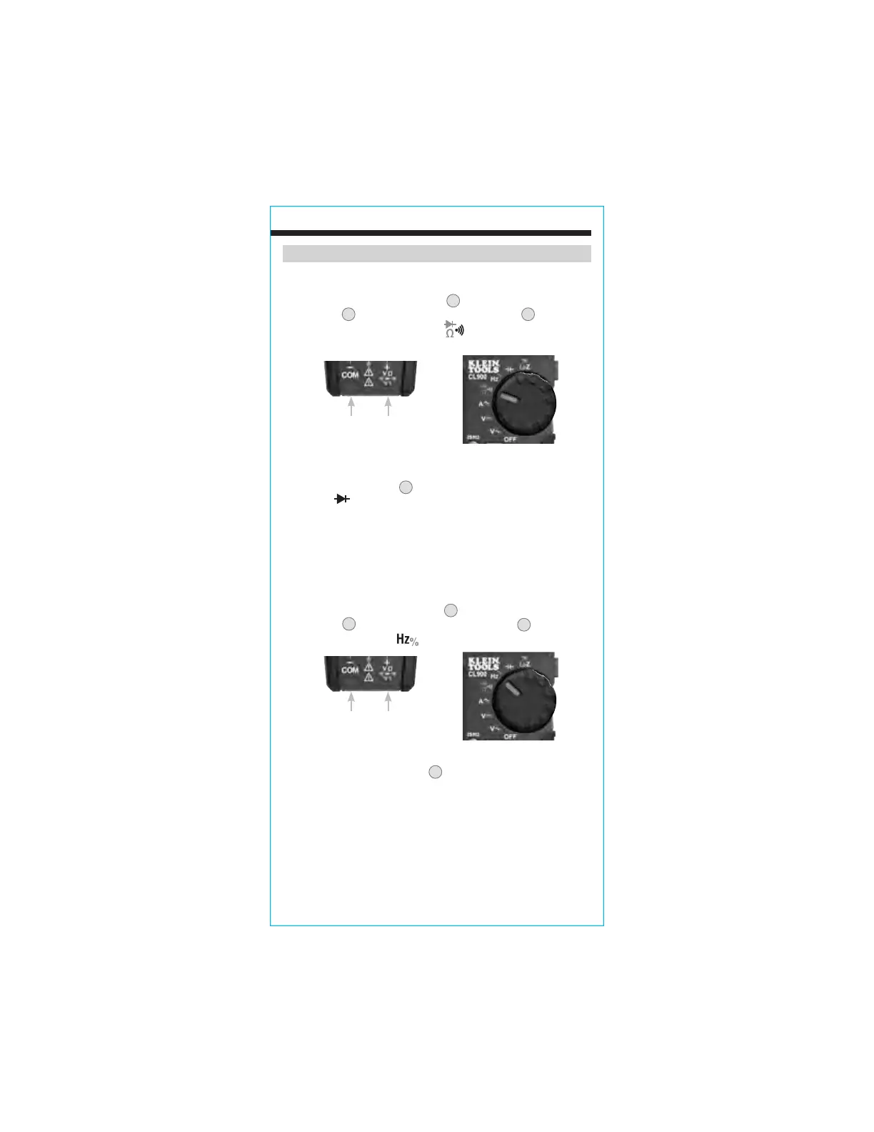
DIODE TEST
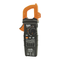
1. Insert RED test lead into VΩ jack
5
, and BLACK test lead into
COM jack
4
, and rotate function selector switch
2
to the
Continuity/Resistance/Diode-Test
setting.
NOTE: The meter defaults to Continuity testing in this mode. Press
the SEL/DC ZERO" button
9
twice to enter Diode testing mode. The
Diode icon will appear on the display.
2. Touch test leads to diode. A reading of 200-800mV on display
indicates forward bias, "OL" indicates reverse bias. An open
device will show "OL" in both polarities. A shorted device will
show approximately 0mV.
FREQUENCY / DUTY-CYCLE
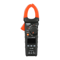
1. Insert RED test lead into VΩ jack
5
and BLACK test lead into
COM jack
4
, and rotate function selector switch
2
to the
Frequency/Duty-Cycle
setting.
OPERATING INSTRUCTIONS
NOTE: : The meter defaults to Frequency testing. To test Duty-Cycle,
press the "SEL/DC ZERO" button
9
once. Ensure that the appropriate
icon (either Hz or %) appears on the display.
1. Measure by connecting test leads across the circuit.
Black lead Red lead
Black lead Red lead
www.GlobalTestSupply.com
Find Quality Products Online at: sales@GlobalTestSupply.com