10
CONNECTIONS
Electrical connection
The electric connection must only be performed by qualified staff, with respect to all general and local Safety Standards in force.
Check that the power supply voltage and frequency correspond to 220V – 50 Hz.
Appliance safety is obtained when the same is correctly connected to an efficient earth plant.
In the electric connection to the mains power supply, envision a differential magnet circuit breaker switch at 6 A – Id 30 mA with relevant breaking load. The
electric connections, including the earth, must be made after the voltage has been removed from the electric plant.
When realising the system remember that the cables must be placed in an unmovable and away from parts subject to high temperatures. During the final
wiring of the circuit, only use components with a suitable electric protection rating.
KLOVER srl declines all responsibility for injury to persons, animals or damage to objects deriving from the failure to connect the network to
earth and failure to comply with the IEC Standards.
The electronic control unit manages and controls all thermo stove functions always assuring excellent functioning of the entire appliance.
Control of any coupled boiler
If the Bi-Fire Mid thermo stove is to be coupled with another boiler already installed in the system (e.g. wall-hung gas boiler), it must be ensured that when
the pellet/wood thermo stove functions for the heating system, the boiler stops. This is so that the calories in the two appliances installed in the system to not
have to be added. This is why our set-up intervenes on the coupled boiler when the thermo stove heating pump starts. In this way, there will never be two
boilers functioning simultaneously in the same system. The coupled boiler will always be able to be used for the production of domestic hot water.
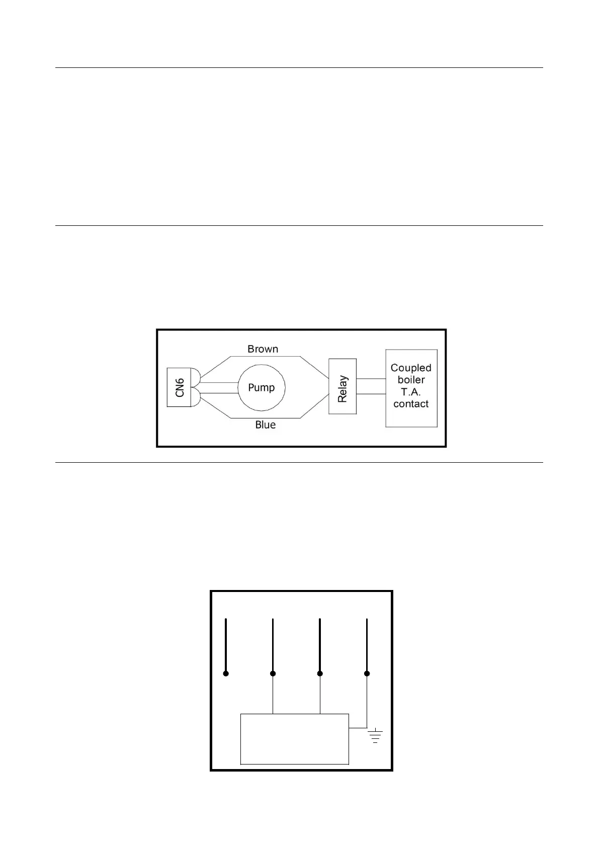
The two wires prepared on the back of the thermo stove (blue and brown wires), on outlet they will have a voltage of 220 V when the thermo stove
pump functions, no voltage when the pump is at a standstill.
It is therefore easy to connect the two wires to a relay that will control the Room Thermostat inlet of the coupled boiler.
Control of any 3-way valve for the DHW circuit
The Bi-Fire Mid thermo stove is equipped with a control as per standard for any motorised 3-way valve to be installed on the domestic hot water circuit. A
cable with 4 wires escapes from the rear part of the thermo stove, which can be used to control this valve. The four wires in the cable have different colours,
precisely:
Blue wire = COMMON TO 3-WAY VALVE
Black wire = BI-FIRE THERMO STOVE SIDE
Brown wire = GAS BOILER SIDE
Yellow/green wire = EARTH
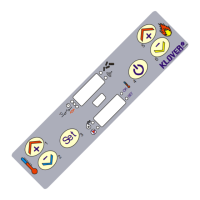
Below find a connection example using a 3-way valve with spring return. Remember that the hydraulic connection must be made in a way that when the
valve is at rest, the water passes from the gas boiler. Only when the thermo stove temperature is sufficient (value set from control panel), the 3-way valve is
powered and therefore closes the gas boiler circuit and opens the Bi-Fire Mid thermo stove circuit.
BROWN
YELLOW/GREEN
BLUE
BLACK
3-WAY VALVE
with spring return
TYPE 1
closing phase
neutral/common
opening phase
earth mass
N.B.: the brown wire can be used to control any service relay.