5
Caution
Both stop pins must be installed to prevent actuator damage.
4. If the stop pins are positioned as required, you may leave them in place. If
not, remove the appropriate pin(s) and place it in the correct slot.
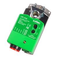
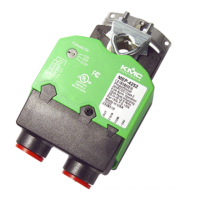
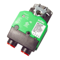
Mounting
The controller will be mounted directly over the damper shaft. A minimum shaft
length of 1-3/4” (45 mm) is required. The base of the controller must contact the
mounting surface to allow installation of a bracket to prevent the controller from
rotating.
Note:
The controller should be mounted close enough to the Pitot tubes to allow a
maximumn 24” length of tubing to reach the controller inputs.
Proceed as follows:
1. Back out the set screws in the shaft collar so the shaft can fit through the collar.
2. Place the controller on the damper shaft in the approximate final position.
3. Position the non-rotation bracket and secure it using #8 or #10 self-tapping
screws. Make certain the notch in the bracket securely engages the Lock tab
on the controller. (Refer to Illustration 1.)
4. Manually position the damper in the full open position.
5. Adjust the drive hub as follows:
A. If the damper rotates counter clockwise to close, depress the gear disen-
gagement button and rotate the drive hub to the full clockwise position
then release the button.
B. If the damper rotates clockwise to close, depress the gear disengagement
button and rotate the drive hub to the full counter clockwise position then
release the button.
6. Tighten the two set screws in the drive hub to approximately 50–inch pounds
(5.65 N-m) to lock the hub to the shaft.
Wiring
The controller comes with a removable conduit plate. The plate provides two
1/2” female threaded conduit couplings. If conduit is to be used, note the
following:
◆ The conduit plate may be removed by removing the two screws that secure
the access cover and removing the cover. Connect the required conduit and
replace the plate in the controller housing.
◆ The plugs may also be sliced to allow wiring to enter the controller with a
minimum of outside contaminates.
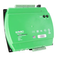
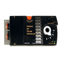
KMD-7001/7002/7003 Direct Digital Controller Installation & Operation Guide Installation
 Loading...