7/11/2005 VERSION 2.0 24
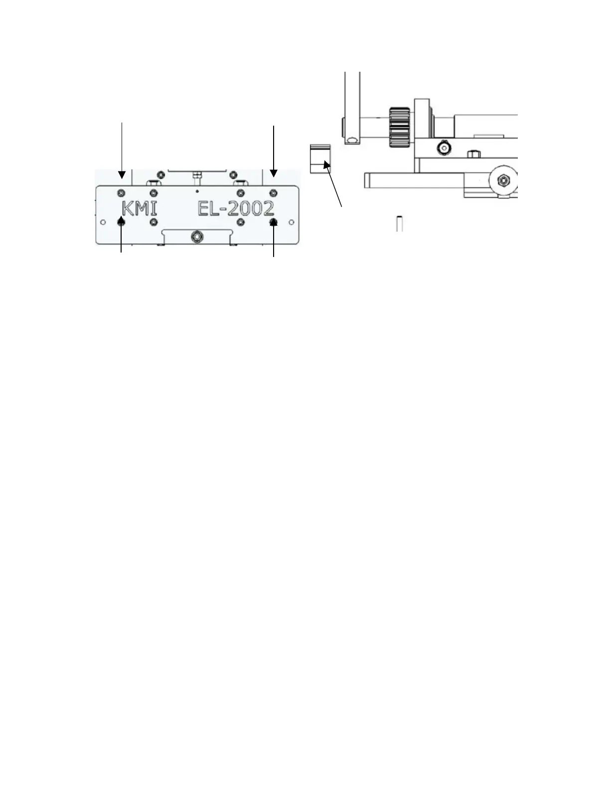
Figure 11-2: Removing the four outermost screws (left) will allow for the removal of the rack gear and the
rack spacer (right). Removal of the gear/spacer on the left and right of the front plate will allow for crimp
handle adjustment.
Rotate the crimping handle to the desired angle and replace the left side rack gear and spacer taking care to
realign gear teeth just as they were before (four spaces down in the case of Figure 11-1). Be sure to have
the rack gear situated so that the notched end of the gear is facing up (see Figure 11-1). Replace the rack
and spacer on the right side also and make sure all four socket head screws are tight. Turn the crimp depth
adjustment knob counterclockwise until it meets the nut above it. Replace blue cover and continue
operation as dictated in Section 7.
11.3. PROFILE CURVATURE ADJUSTMENTS
*Be sure the material specifications identified in Section 3 are closely adhered to. Excessively strong
or hard material (base metal) often leads to tearing or other unpredictable results. *
In order to achieve the proper elbow profile, minor adjustments may need to be made to the side knives and
overall crimp depth. Drastic changes in the positions of the adjustment screws will cause even more drastic
changes in the resulting crimp. Turn the adjustment screws in small increments and utilize multiple test
blanks in order to achieve the desired elbow.
(Front view)
(Top View)