7/11/2005 VERSION 2.0 25
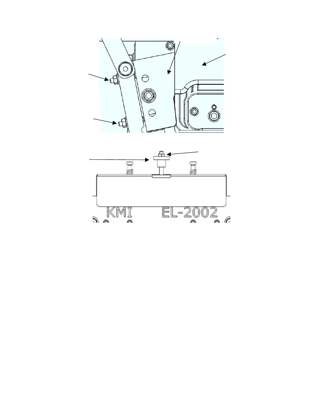
Figure 11-4: This figure shows the location of the two adjustment screws for the left side knife.
Figure 11-5: This figure shows the location of the crimp depth adjustment knob.
The crimp depth can be altered by adjusting the knob shown in Figure 11-5. To make the crimp deeper (on
the top as well as the sides), turn the knob counterclockwise slightly. To make the crimp shallower, turn
the knob clockwise.
** It should be noted that the long setscrew itself WILL NOT TURN. It has been locked in place and
will break if it is turned. Loosen the lock nut and only turn the adjustment knob. Once adjustment
has been achieved, tighten the lock nut against the knob with slight pressure. **
DO NOT TRY TURNING THE SET SCREW WITH HEX WRENCHES OR VICE GRIPS.
FAILURE TO HEED THIS WARNING WILL BREAK THE SET SCREW.
Complete adjustment of the machine may require adjusting all four side adjustment screws and the crimp
depth knob. Multiple practice blanks might be needed to achieve the desired profile and the operator will
most likely require a some practice adjusting the machine. If there is any problem understanding the
sequence or the function of any of the adjustment knobs, the factory or distributor should be contacted for
assistance in adjustments.
* Knudson Mfg, Inc. recommends the customer send in several samples of downspout to be formed
into elbows. The factory will use the samples to adjust the machine and produce as many finished
elbows as possible to ship with the machine. *
Lower left
adjustment
screw
Upper left
adjustment
screw
Crimp depth
adjustment
knob
Left side knife
Top knife
Lock nut