Do you have a question about the Kobelt 6505 and is the answer not in the manual?
Provides contact details for Kobelt Manufacturing Co. Ltd., including phone, fax, email, and website.
Details safety alerts, notices to installers, and product hazards for safe operation and installation.
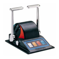
General overview of the 6505 electronic control head, its functions, and key components.
Details technical data like handle travel, output, terminals, ambient temperature, finish, and weight.
Provides the key for understanding model variations based on control, finish, and handle options.
Instructions for physically mounting the control head securely on a flat surface, considering flexing and room.
Guide to making electrical connections, including cable specifications, shielding, and wiring for signal integrity.
Instructions for setting DIP switches to assign network addresses to each control head for proper communication.
Steps to verify correct operation after installation, including power-up checks and clutch engagement tests.
Explains the functions of the four membrane buttons: Station Select, Station Lock, Throttle Override, and Synchronizer.
Outlines recommended preventative maintenance tasks for quarterly checks and bi-annual inspections.
Step-by-step guide to centering the potentiometer and calibrating the output for accurate control.
Instructions for correctly wiring potentiometers to connector P1, referencing terminal connections.
Specifies approved greases for lubricating the detent track to prevent premature wear.
Lists essential spare parts and kits recommended to be kept on hand for service and maintenance.
Details the warranty coverage, exclusions, and procedures for making a claim.
Provides detailed diagrams with measurements for control head installation and mounting.
Shows an exploded view of the control head with numbered components and refers to the detailed parts list.
Provides a template for the correct cut-out dimensions for mounting the control head on a surface.
The Kobelt 6505 Electronic Control Head is a compact electronic control unit designed for marine applications, providing precise control over engine throttle, clutch engagement, or propeller pitch. It communicates via CANbus and offers a 10-bit digital output proportional to the handle position. This control head is an integral part of Kobelt's Mighty Mariner controller system.
The primary function of the 6505 control head is to translate the operator's handle movements into electronic signals for controlling marine propulsion systems. It features a handle with three distinct detent positions: one at Top Dead Center (TDC) for neutral, and two others corresponding to clutch activation points for both ahead and astern propulsion. This design ensures clear tactile feedback for clutch engagement.
Beyond basic throttle and clutch control, the unit incorporates a keypad with four membrane buttons, enabling several advanced operational features:
The 6505 control head is designed for ease of use and robust performance in a marine environment. Its compact design and intuitive keypad simplify operation. The detented handle positions provide clear tactile feedback for critical control points. The unit is designed for direct mounting to a flat, strong, and stiff surface, ensuring stability during operation. Electrical connections are made via two cable glands, accommodating 0.20 inch [5 mm] to 0.47 inch [12 mm] OD cable with 18 AWG conductors. Shielded twisted pair cable is recommended for signal integrity. Up to eight control heads can be connected in a 'daisy chain' configuration, with the last unit requiring a 120 ohm resistor between data terminals.
Regular maintenance is crucial for the longevity and reliable operation of the 6505 control head. The manual outlines a preventative maintenance schedule:
If the potentiometer is replaced or its setting becomes disturbed, a calibration procedure is required to center the output:
Kobelt recommends keeping a minimum set of spare parts on hand, including:
It is advised that any service work be performed by a factory-authorized service representative. The manual includes an appendix with a detailed parts list and installation dimensions for reference.
| Brand | Kobelt |
|---|---|
| Model | 6505 |
| Category | Controller |
| Language | English |