6505 Control Head Kobelt Manufacturing Co. Ltd.
Rev A mnl6505.docx 9 of 18
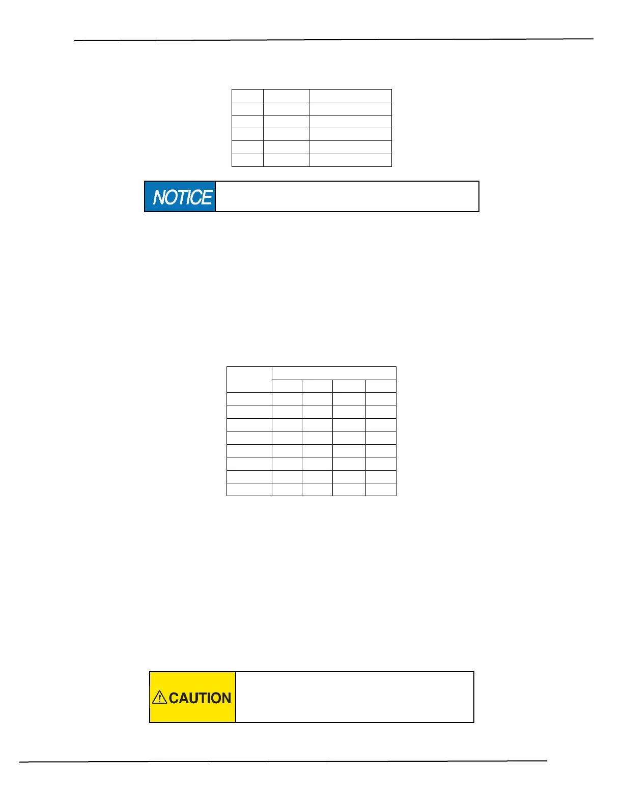
Table 1: Connector P2 termination
The last control head must have a 120 ohm resistor between
terminals 3 & 4 or network communication will be lost.
When connecting the Sonalert buzzer to connector P4, ensure that the positive wire is connected to
terminal 1.
Before completing the wiring, remember to leave enough extra cable length to permit removal of the
control head without disconnection the wiring.
3.3 DIP SWITCH SETTINGS
The network address of each control head is assigned via a four pole DIP switch on the circuit board. Set
the switches as shown in the table below:
Table 2: Control Head Address
Set each control head to a different address number. Ensure that number 1 is assigned to the bridge or
main station as this is the unit that will automatically get control after power up.
3.4 FUNCTIONAL TEST
Upon power up, the main station sonalert will start beeping and the STATION SELECT lamp will blink. If
this is not happening, inspect the wiring. After successful power up, press the STATION SELECT switch to
assume control from the current station.
Once in control, test that the clutches engage and disengage as expected and that the full range of
throttle control is available.
Do not put the equipment into service until the
control head has been tested. The Functional Test
should be carried out while the equipment is safely
secured.