6505 Control Head Kobelt Manufacturing Co. Ltd.
Rev A mnl6505.docx 11 of 18
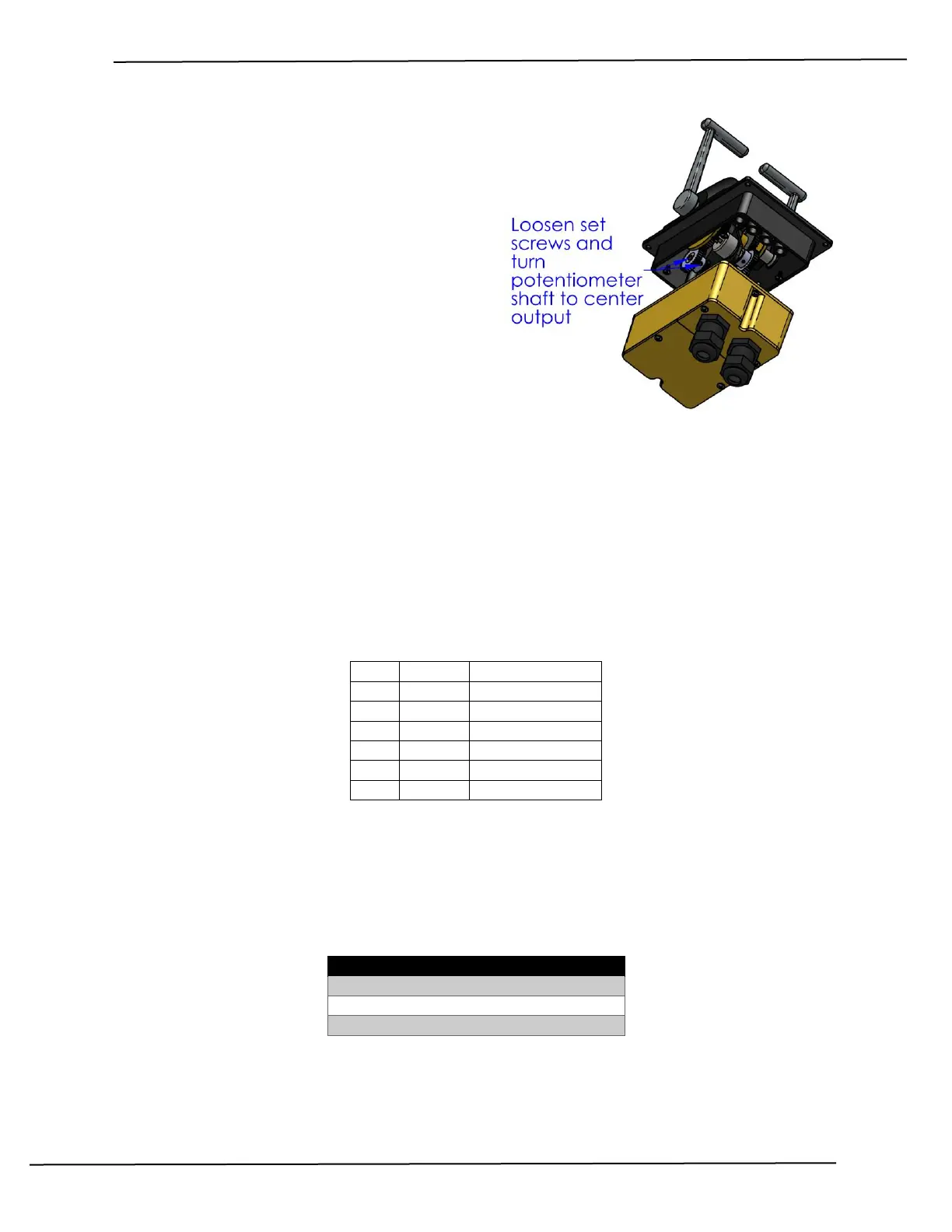
3. Locate the potentiometer in need of
centering.
4. Connect a multimeter to the Pot – (white
wire) and the Pot Wiper (green wire). Set the
meter to read resistance.
5. Loosen the two locking set screws on the
pinion gear with a 1/16-inch Allen key.
6. Using a short flat head screwdriver, rotate the
potentiometer shaft until the meter reads
half of the rated output (2500 ohms for a 5K
potentiometer).
a. Note: compare the output between
the wiper and Vref+ to wiper and
Vref-. Adjust the shaft to balance.
7. Tighten the two locking set screws and replace the cover.
After centering the control head, calibrate the throttle output to the 6525 controller. To perform this
function set DIP switch #4 to the OFF position and follow the prompts from the 6525 propulsion
controller. After completion, return DIP switch #4 to the ON position.
5.3 POTENTIOMETER CONNECTION
The control head potentiometers are wired to connector P1. When replacing these devices ensure that
they are connected as per the table below:
Table 3: Connector P1 Termination
1. The potentiometers are wired mirror image to synchronize the outputs.
5.4 LUBRICATION
The track the detent runs along on the detent plate must be lubricated to prevent premature wear. Use
a grease with MoS
2
additives for best results. The following greases are approved:
Table 4: Approved Lubricants