6505 Control Head Kobelt Manufacturing Co. Ltd.
Rev A mnl6505.docx 8 of 18
3 INSTALLATION
3.1 MECHANICAL
The control head must be mounted on a flat surface, strong and stiff enough to withstand the operating
forces imposed during normal use without excessive flexing. Choose a location that has sufficient room
for the handle to swing to both extreme positions. Use the template at the back of this manual to make
the correct cut-out on the mounting surface.
The control head is equipped with (4) four clearance holes for #10 (M5) screws inserted from
underneath for direct mounting to the dash. Ensure the unit is securely fastened, preferable with an
anaerobic thread locker such as Loctite 243.
3.2 ELECTRICAL
The 6505 control head is equipped with two cable glands with which to make the electrical connections.
Use 0.20 inch [5 mm] to 0.47 inch [12 mm] OD cable with 18 AWG conductors for external connections
to the engine controller. The cable must be twisted pair, shielded to protect signal integrity. Use
ferrules on the cable ends for all wire connections.
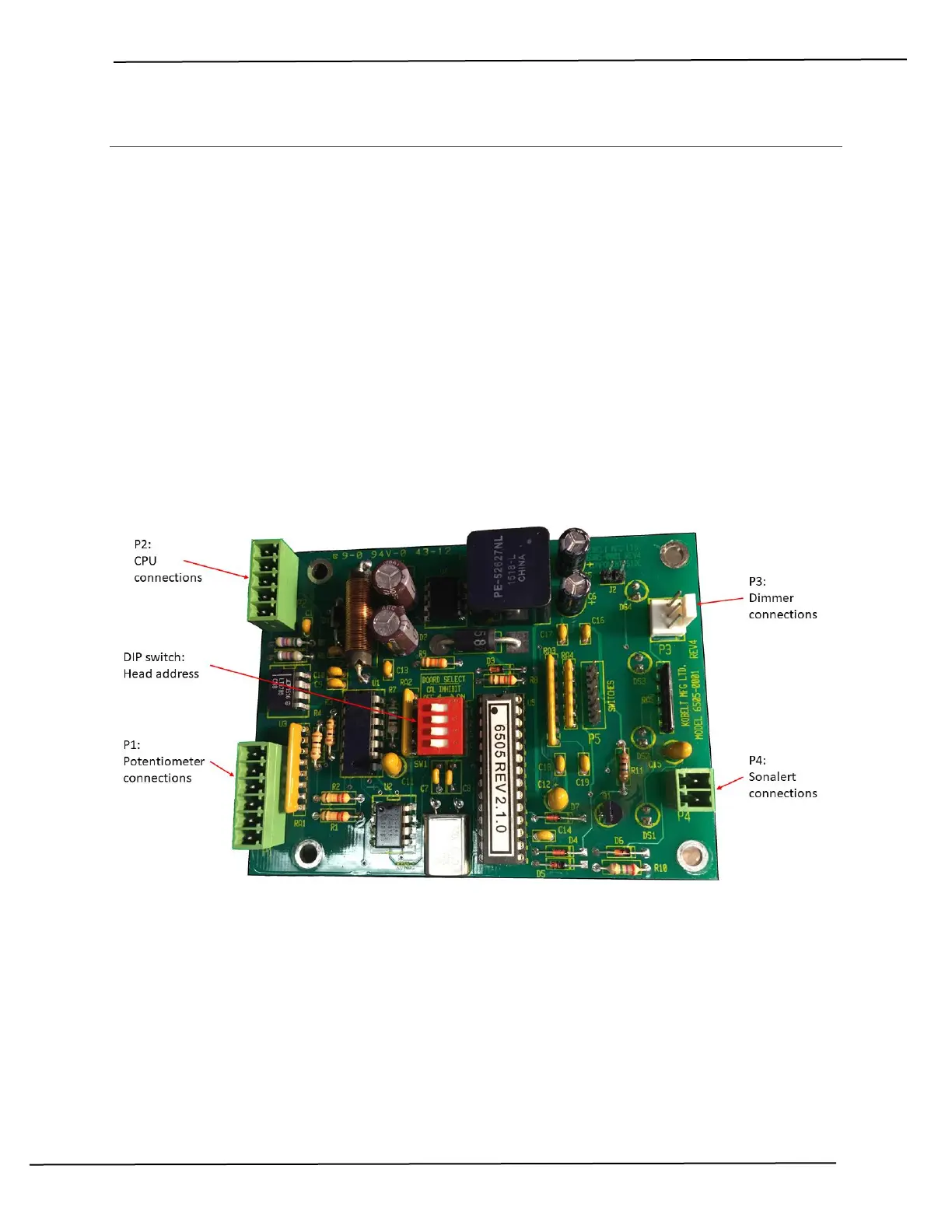
Plug connectors are supplied on the board of the control head for making the connections to the circuit
board. No power connections are required as the unit receives power through the network from the
controller. Up to eight control heads can be connected in ‘daisy chain’ fashion to connector P2. The last
control head must have a 120 ohm resistor installed between the data terminals (pins 3 & 4).