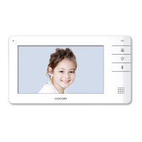
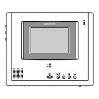
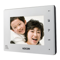
① Monitor screen (LCD)
② Speaker ③ Microphone
④ Monitor button
⑤ Motion lamp
⑥ Speak button
⑦ Open door button
⑧ Brightness adjustment volume
⑨
Call volume adjustment switch
⑩
Speaking volume adjustment switch
⑪ DC door switch terminal
⑫ Camera terminal
⑬ Extension monitor terminal
⑭
Color adjustment volume
⑮
Power input section
Name and functions of each part
■ The front side
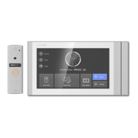
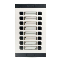
■ Door Camera components
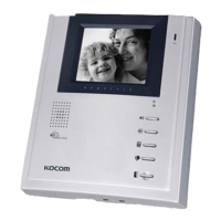
■ The Back side
Components of product
Components of product
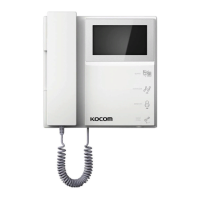
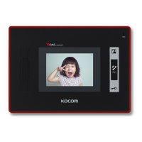
■ Monitor components
Product functions and features
Installation location
■ Specifications■ Max wiring distance
Specifications
Model number
KCV-D372
TYPE
Line type
Distance
■ Monitor installation location
■ Caution of camera installation
■ Camera installation location
■ Directly connecting cut-off power cord with power wire
1) Remove wall-hanger bracket metal behind monitor.
2) Install wall- hanger bracket metal on 1 type box or wall with attached Vis.
3) Connect wiring to monitor back terminal referring to product connection diagram.
4) Hang monitor on wall-hanging metal, and fix monitor on wall- hanger bracket metal
using attached Vis.
5) Plug monitor’s power plug into consent and check to see if the power switch is [ON]
on the left side of monitor.
■ Monitor installation
connection condition railway line type and distance
1. Display product working condition with OSD
2. When no signal on image, converts to standby condition
3.
Very low consumption of electric power in standby
4. Use of Digital 7”LCD Panel
5.
Nonpolar 2 wire method between camera and monitor
6. Extension monitor’s 2 wire method
7. Long distance wiring
8. Can connect door opener to monitor and camera
9. Automatic confirmation tool of connection between camera and monitor
 Loading...