KV1000 Constant Temperature Kinematic Viscosity Bath
Operation and Instruction Manual
- 9 –
4.4. Recommended Accessories
Withdrawal Bulb (K22090)
Used to pull sample into viscometer tube
Rubber Stopper, pk/12 (K23311)
To hold sample after it is pulled through the viscometer prior to test
Cooling Coil (K23377-01000)
Permits circulation of water or refrigerated coolant for operation at near ambient temperatures. Installs in top plate. Hose-barb inlet
and outlet connections for water or refrigerated coolant are located at the top of the bath. Secure with copper wire to prevent the
tubing from disengaging from the connection.
5. Operation
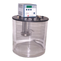
5.1. Bath
NOTE: Ensure the Borosilicate glass jar is not cracked or
broken. DO NOT USE the jar if there is any damage.
Fill the bath with the appropriate heat transfer fluid based
upon the testing temperature. Fill the bath with the
medium to 2" (5 cm) from the top of the bath to allow room
for fluid expansion. This will provide the proper depth for
immersing the viscometers and allow for thermal
expansion.
5.2. Power
WARNING: Do NOT turn the power on unless the bath is filled with the proper medium; otherwise, damage may occur to the unit
and the warranty would be void.
An IEC power cord is provided with the KV1000 Bath. This power cord should be plugged into the IEC receptacle on the rear of
the controller and then plugged into a properly grounded outlet. Make sure that the power outlet is the same voltage and frequency
indicated on the identification label on the back of the Controller.
The use of an extension cord is not recommended. However, if one is necessary, it must be properly grounded and capable of
handling the total wattage of the unit. The extension cord must not cause more than a 10% drop in voltage to the Circulator.
Once the unit has been connected to an appropriate electrical outlet, place the Circuit Breaker/Power Switch on the rear of the
Controller in the ON position. Four decimal points (….) will appear on the digital display. DO NOT place the Power Switch on the
front of the Controller ON until the Safety Set has been adjusted to the desired temperature.
Indicated Voltage