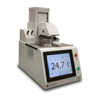
K71000 Automatic PMCC Flash Point Analyzer
Operation and Instruction Manual
K71000-Manual -24-
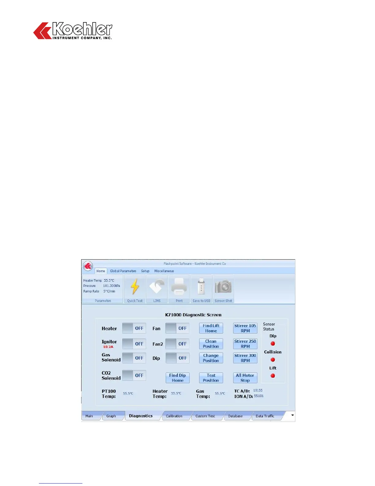
7. Diagnostic Screen - Clicking on the Diagnostics Tab located at the Lower Tab Section of the Main
Menu will bring up the K71000 Diagnostic Screen. The Diagnostics screen allows the user to check
proper functioning of the following components by toggling an On/Off Switch:
a. Heater
b. Ignitor - Note also that there is an indicator below that displays the intensity of the ignitor in Amps
c. Gas Solenoid
d. CO
2
Solenoid
e. Fan - For cooling electrical components
f. Fan2 - High Powered fan for cooling heating block after test
g. Dip
The Diagnostics Screen also allows the user to test the functionality of the numerous mechanical
functions of the analyzer. See descriptions below:
a. Find Dip Home - Brings flame dip mechanism to home position
b. Find Lift Home - Brings mechanical lift to Home Position (also considered test position)
c. Clean Position - Brings mechanical lift to Clean Position (highest position)
d. Change Position - Brings mechanical lift to Change Position (middle position)
e. Test Position - Brings mechanical lift Test Position (home position)
f. Stirrer 105 RPM - Rotates Stirrer Motor at 105 RPM (ASTM D93, Procedure A)
g. Stirrer 250 RPM - Rotates Stirrer Motor at 250 RPM (ASTM D93, Procedure B)
h. Stirrer 300 RPM - Rotates Stirrer Motor at 300 RPM (Maximum RPM)
i. All Motor Stop - Stops Stirrer Motor
A Sensor Status bar can also be found on the right hand side of the Diagnostic Screen. The lights
change from Red to Green when that particular sensor is activated. For example when the Collision
Sensor is activated by an object coming in contact with the mechanical lift during descent, the light
will briefly change from Red to Green.
Figure 13: Diagnostic Screen