TP-6805 8/15134 Section 7 Disassembly/Reassembly
Note: Obtain new exhaust gaskets before removing the
muffler.
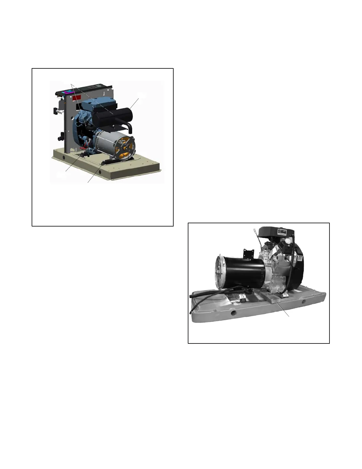
17. Disconnect the muffler from the engine at the two
flange connections and remove the muffler. See
Figure 7-20.
1. Exhaust flanges (qty. 2)
2. Muffler
3. Alternator vibromounts (qty. 2)
4. Engine vibromounts (qty. 2)
2
1
3
4
Figure 7-20 Muffler and Vibromounts
7.2.3 Generator Disassembly
18. Disconnect the following alternator wiring inside
the controller junction box. See the wiring
diagrams in Section 8.
a. Disconnect lead 55 from the mini-breaker on
the controller.
b. Disconnect P2 from the controller.
c. Disconnect leads 2 and 3 from neutral stud L0.
d. Disconnect leads 1 and 4 from the circuit
breaker.
19. Remove the bolts securing the two alternator end
vibromounts to the skid. Loosen the two engine
vibromounts. See Figure 7-20.
20. Raise the alternator end of the generator set
enough to place a wood support beneath the rear of
the engine. The wood support must be long
enough to span the opening in the base. See
Figure 7-21.
Note: Use a hoist or lifting device that is rated for
the weight of the generator set. See
Section 7.1.
img_0160
1
1. Engine support
Figure 7-21 Wood Support for Engine (RESA shown)

 Loading...


