TP-5606 6/02 Controller Troubleshooting 5-7
Stopping
Normal Stop—A normal stop is initiated by rocking the
Start/Stop Switch on the controller front panel to the
Stop position and then releasing the switch. Holding
the switch in the Stop position energizes the AH
relay, causing further, unnecessary heating of the
air heater. In the Stop position, the Start/Stop switch
provides a ground through two blocking diodes to
energize the K4 relay (LED4 lights). The normally open
K4A contacts then close, latching the K4 relay in an
energized condition.
At the same time, normally closed K4B contacts open to
de-energize the FP (fuel pump) motor and the K25 relay.
The normally open K25 contacts then open to
de-energize the FS (fuel supply) solenoid, turning off the
flow of fuel. With the fuel supply and fuel pump both
turned off, the engine turns off.
With the engine turned off, the generator output decays
and causes relays K1 and K5 to de-energize (LED1 and
LED5 go out). The normally open K1D contacts then
open, de-energizing the K2 relay (LED2 goes out) and
opening the normally open K2 contacts to interrupt
power to the remaining controller relay circuits,
including relay K4. As a result, the latch-up of the K4
relay is broken to return the controller circuits to a normal
prestart condition.
FROM SAFETY
SHUTDOWN
SWITCHES
K5
K4A
LED4
K4
K2
SDR
12 VDC
AH
AIR HEATER
AH
M
FS
S
10 A.
K25
K25
FP
10 A.
START
STOP/
PREHEAT
K1C
K1D
K1E
K2
K20
K3
K4B
K2
K3
K20
S
B.C.
ALT
LED3
LED2
OP
WT
HR
K1A
VOLTAGE
REGULATOR
LED1 LED5
K1 K5
HR
BV
GEN
ON
REMOTE PANEL
K1F
K1B
SDR
OVERSPEED
PROTECTION
CIRCUIT BOARD
MAIN FIELD
8A.
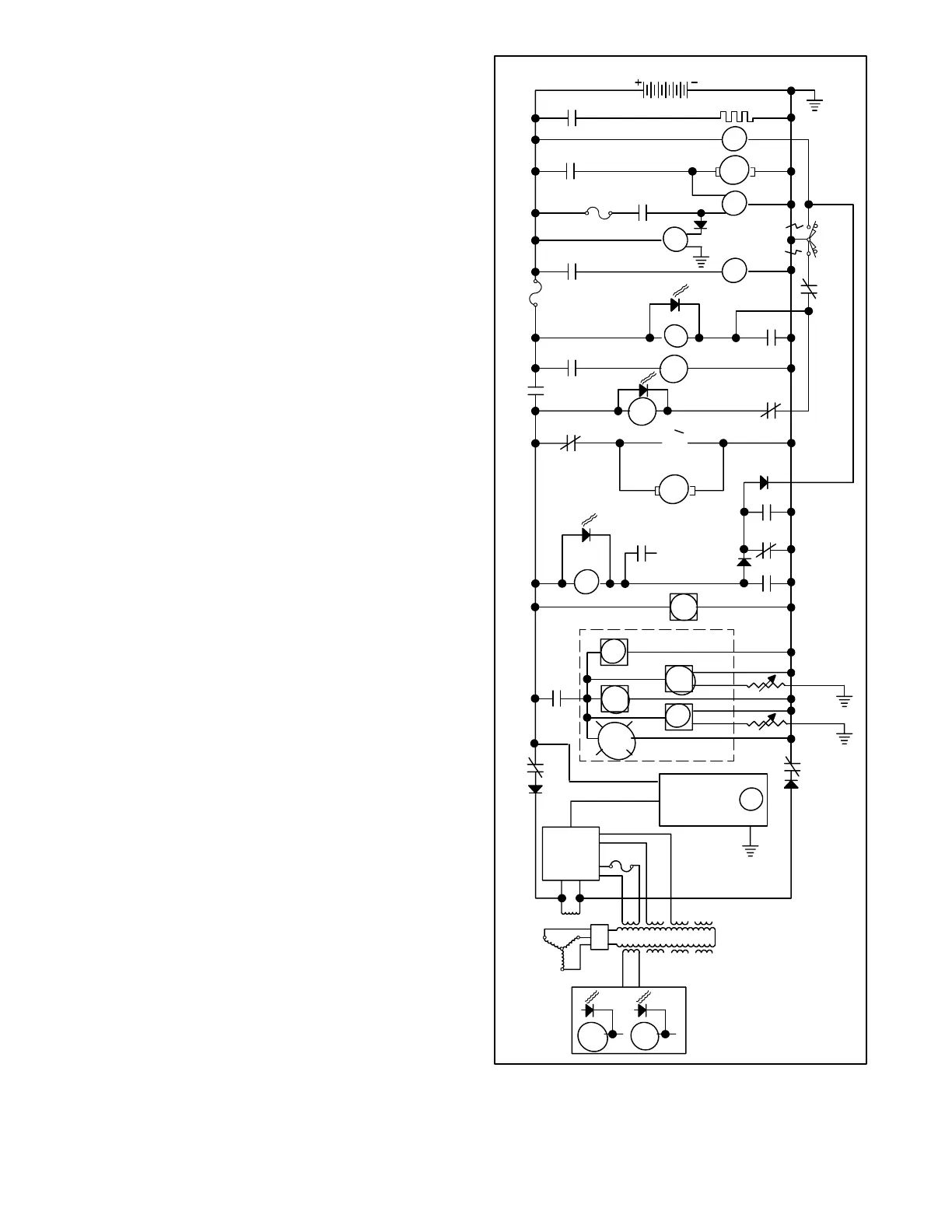
Figure 5-7. Three-Phase Generator Sequence of
Operation, Stopping
 Loading...