Generator/Controller Troubleshooting 6-1TP-5606 6/02
Section 6. Generator/Controller
Troubleshooting
The section contains flow charts to troubleshoot the
generator set including the controller circuit board.
Before beginning the troubleshooting, read all safety
precautions at the beginning of this manual. Additional
safety precautions are included with the tests; DO NOT
NEGLECT THESE PRECAUTIONS.
Controller Circuit Board
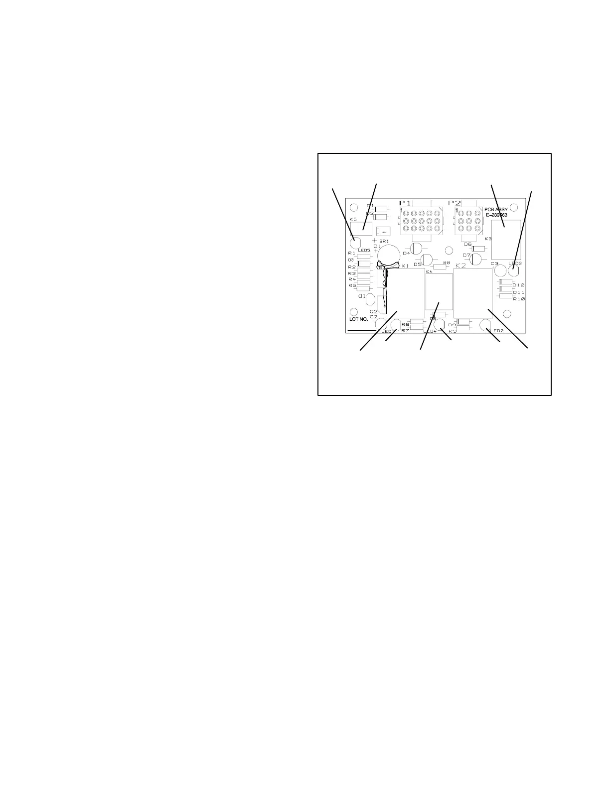
The controller circuit board is equipped with LEDs (light
emitting diodes) to indicate the presence of relay coil
power and aid in circuit board and generator fault
detection. See Figure 6-1.
When K1, K2, K3, K4, or K5 relays are receiving power,
the corresponding LED will light. The LED does not
indicate whether the relay coil is good or bad. This
conclusion can only be reached through analysis of the
fault.
Use the flow chart (Figure 6-2) as an aid in
troubleshooting the generator set.
Where a check or test is referenced, go to the procedure
for detailed instructions.
E-239563-
K4
K3
K2
K1
K5
LED1
LED3
LED4
LED2
LED5
Figure 6-1. Controller Circuit Board
E-239563
 Loading...