Component Testing and Adjustment 7-3TP-5606 6/02
12 Volt
Battery
Exciter
Field
-- +
DC
AM
10-Amp
P5--12
Fuse
P5--10
P4
To Controller
P4
P6 P7
Three-Phase Generator
Single-Phase Generator
TP-5414-6
D.C.
A.M.
Brushes
Slip
Rings
+-
12 Volt
Battery
Rotor
Voltage Regulator
PowerBoost IIIE
Black (+)
White (-)
-+
10 AMP
FUSE
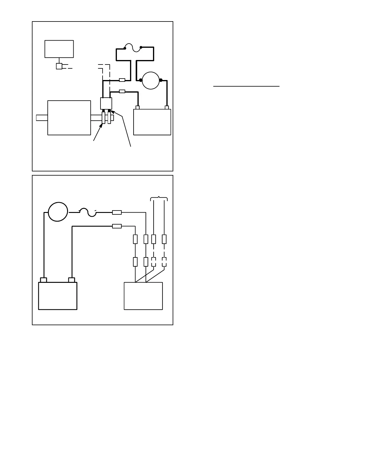
Figure 7-2. Separate Excitation Connections
3. The approximate ammeter reading should be
battery voltage divided by specified rotor
(single-phase generator) or exciter field
(three-phase generator) resistance. For
resistances, see Specifications--Generator in
Section 1.
E
ample:
12 Volts (Battery Voltage)
4.7 Ohms (Rotor or Exciter
Field Resistance)
=
2.6 Amps
(Rotor Current)
4. Start engine and check that ammeter reading
remains stable. An increasing meter reading
indicates a shorted rotor or exciter field. A
decreasing meter reading to zero or an unstable
reading suggests a running open (see Rotor or
Exciter Field heading later in this section). If
ammeter is stable proceed to Step 5.
5. Check for AC output across stator leads (see
Stator heading later in this section) and compare to
readings in Specifications--Generator of Section 1.
If readings vary considerably from specified
values, a faulty stator is likely (see Stator heading
later in this section).
6. If rotor and stator test good in prior steps, the
voltage regulator is probably defective. (Refer to
appropriate Voltage Regulator heading later in this
section.)
NOTE
Stator output voltages found in
Specifications--Generator of Section 1 are based
on a battery voltage of 12 volts. Should actual
battery voltage vary (11-14 volts), resulting values
will also vary.
NOTE
You’ll need to hold the fuel rack in to maintain
engine operation.
 Loading...