TP-7045 3/18c58 Section 9 Paralleling Generator Sets
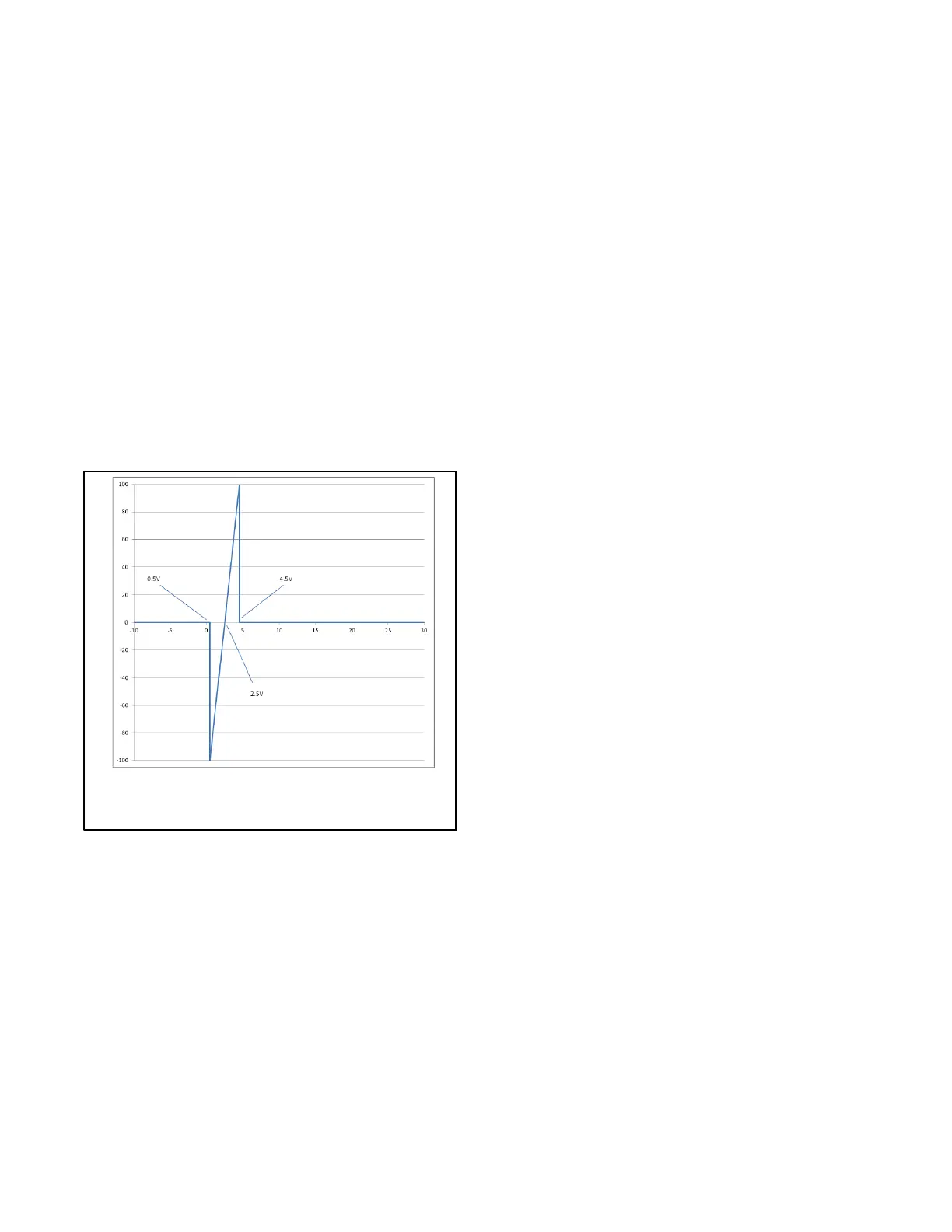
Note: The Voltage Bias can also be controlled by
an external device if the External Bias Inputs
Enabled parameter is true, the Stand Alone
Operation parameter is false, no generators
are visible on the PGEN communications
channel, and the voltage applied to the
voltage bias input is between 0.5V and 4.5V.
The External Voltage Bias Input (VBP and VBN) is
a voltage measuring channel capable of reading
from --10V to 30V DC. The input is normally pulled
down to --3.3V, but can be overridden by applying a
voltage to the input.
The voltage that the controller sees on the voltage
measuring channels is visible in the Analog
Voltage Input Metered Relative Value under the
Programmable Analog Voltage Input 107
parameter heading. The input is polarity sensitive.
The Voltage Bias is interpreted by the controller as
shown in Figure 9-2
Range: -100.00% – 100.00%
Default: 0.00% **Not Writable**
Figure 9-2 Voltage Bias
Synchronizing
Before a generator set can operate in parallel with
another generator set, its electrical output must be
synchronized (matched) to the power source it will
parallel. The parameters that must be matched are:
D Frequency
D Phase Angle
D Voltage
D Phase Rotation (for 3-phase applications)
The synchronizer will issue a breaker close command
when the frequency difference, phase angle, and
voltage difference are within an acceptable range and
the phase rotation matches.
Note: The Decision-Makerr 3500 synchronizer will not
attempt to match voltage, frequency, or phase if
the phase rotation of the bus doesn’t match that of
the generator set.
For PGEN paralleling, the synchronizing is handled
within the Decision-Makerr 3500 controller.
For Remote Speed and Voltage Bias paralleling, the
synchronizing is handled by an external controller,
typically supplied on switchgear.
Real (kW) Load Control
When generator sets are running in parallel (electrically
connected), the load controller controls the generator
sets so each generator set is supplying its proportional
share of power to the load while maintaining rated
frequency. This is isochronous load sharing.
The load controller communicates (analog or digital) to
the other load controllers and determines how much
power each generator set should supply.
For PGEN paralleling, the load controller is within the
Decision-Makerr 3500 controller.
For Remote Speed and Voltage Bias paralleling, the
load control is performed by an external controller,
typically supplied on switchgear.
Reactive (kVAR) Control (Isolated Bus)
When generator sets are paralleled, the voltage output
of each generator set must be equal. Reactive power
control is needed between the generator sets to ensure
that each is supplying its share of the reactive load and
to minimize circulating currents. This can be done in one
of two ways:
1. Active Control (Used in PGEN Paralleling and
some external paralleling). The reactive load
controller communicates (analog or digital) to the
other reactive load controllers to maintain the
same proportional kVAR output while maintaining
the system’s nominal voltage.
2. Passive Control (Used in Droop Paralleling).
The voltage regulators are operated in droop,
biasing the regulator to equalize reactive power
output of the generators. There is no active control
from the controller.
 Loading...


