TP-6071 3/00 37Section 7 Generator Troubleshooting
Between leads Continuity
1 and 4
2 and 5
3 and 6
7 and 10
8 and 11
9 and 12
55 and 66
B1 and B2
1 and 2, 3, 7, 8, 9
1 and 55, B1, and B2
4 and B1 and B2
55 and B1 and B2
Any stator lead and
ground
Yes
Yes
Yes
Yes
Yes
Yes
Yes
Yes
No
No
No
No
No
Figure 7-16 Stator Continuity 3-Phase
5. Check the cold resistance of the stator windings by
connecting the meter leads to the stator leads 1-2,
3-4, etc. See Section 1, Specifications for the
stator resistance values. If the stator resistance
test is inconclusive, perform a megohmmeter test
on the stator as described in the next step.
Note: Consider the stator functional if the
resistance reading (continuity) is low and
there is no evidence of shorted windings
(heat discoloration).
Note: When taking an ohmmeter reading using
lead 55, make the connection prior to the
in-line fuse.
Note: The stator resistance can vary directly with
increased temperature.
If any of the stator readings vary during the previous
checks, replace the stator.
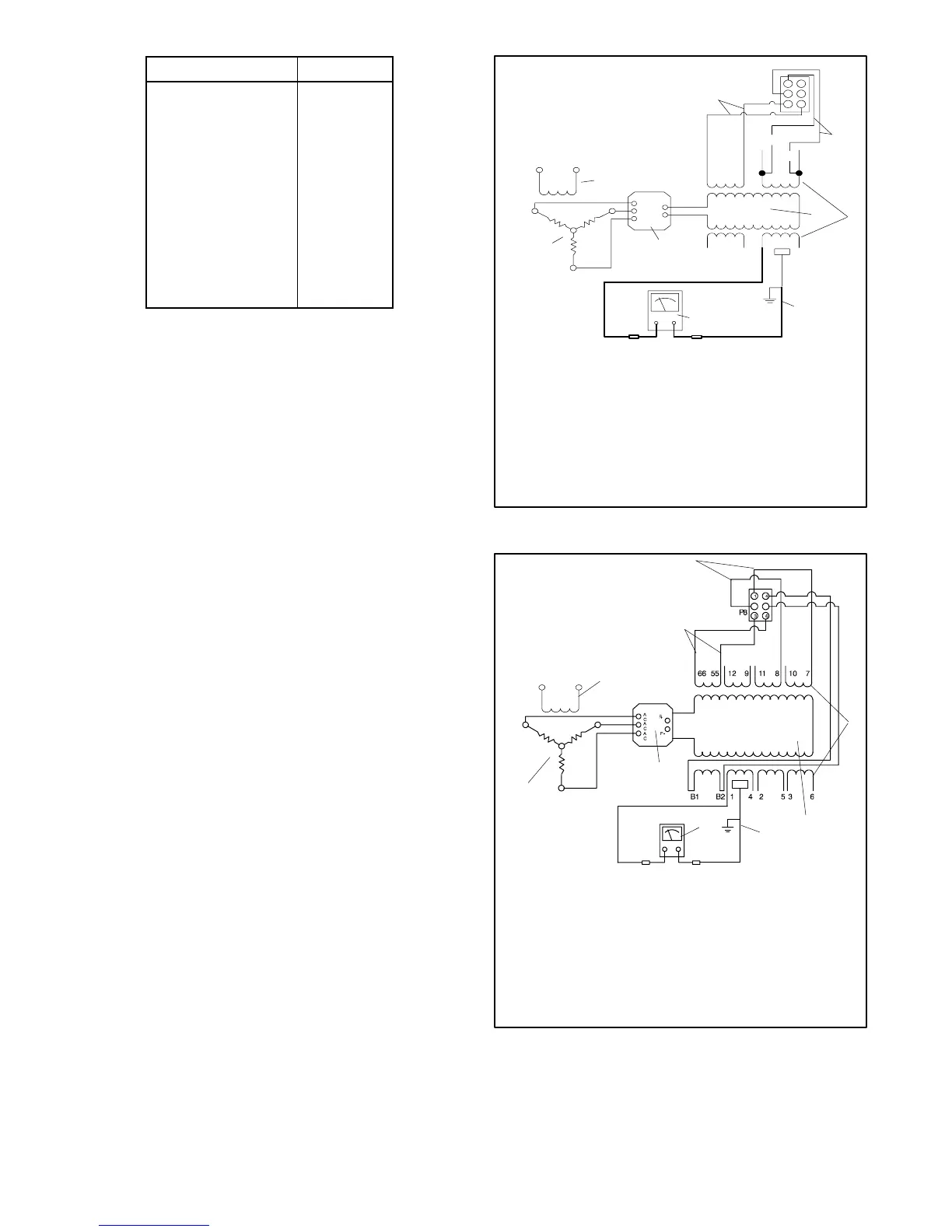
6. Check the stator for a short-to-ground condition
using a megohmmeter. See Figure 7-17 for a
single-phase megohmmeter connections and
Figure 7-18 for three-phase megohmmeter
connections. Apply 500 volts DC to any stator lead
from each winding and the stator frame. Follow the
megohmmeter manufacturer’s instructions for
using the megohmmeter. Repeat the test on the
other leads until all of the stator windings have
been tested. A reading of 1.5 MOhms and higher
indicates the stator is functional. A reading of less
than 1.5 MOhms indicates deterioration of the
winding insulation and possible current flow to
ground; If so, repair or replace the stator.
1
5
6
7
8
9
F+
F--
AC
AC
AC
66
55
3
V4
4
12
B1 B2
F1 F2
1
4
3
6
P8
V1
3
2
4
TP-5983-7
1. Voltage regulator power supply leads
2. Sensing leads (208--240 volts nominal)
3. Stator windings
4. Main field (rotor)
5. Rectifier module
6. Frame connection
7. Megohmmeter
8. Armature
9. Exciter field
Figure 7-17 Megohmmeter Connections on 1-Phase
Stator
TP-5983-7
1
2
6
3
4
5
7
8
F1 F2
9
1. Voltage regulator power supply leads
2. Sensing leads (208--240 volts nominal)
3. Stator windings
4. Main field (rotor)
5. Rectifier module
6. Frame connection
7. Megohmmeter
8. Armature
9. Exciter field
Figure 7-18 Megohmmeter Connections on 3-Phase
Stator
 Loading...


