TP-6071 3/00 41Section 8 Component Troubleshooting
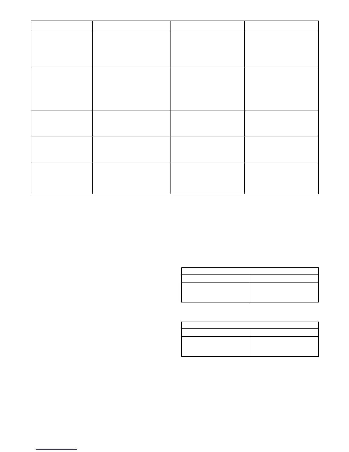
Component Ohmmeter Connections Procedure Results
Main field (rotor) Disconnect the P10 and P11
connectors and connect the
ohmmeter to P10-1 and P10-2
leads.
Place the ohmmeter on the R x 1
scale.
If the resistance readings match
those specified in Section 1,
Specifications, the rotor is
functional. Low resistance—rotor
windings shorted. High
resistance—rotor windings open.
B1/B2 stator windings Connect the ohmmeter to the P11-1
and P11-2 leads. Note: Disconnect
P11 and J11 to perform this test.
Place the ohmmeter on the R x 1
scale.
If the resistance readings match
those specified in Section 1,
Specifications, the B1/B2
windings are functional. Low
resistance—B1/B2 windings
shorted. High resistance— B1/B2
windings open.
P1 ground connection Connect the ohmmeter to the P1-9
and ground.
Place the ohmmeter on the R x 1
scale.
If functional—zero ohms
(continuity). Any other reading
indicates a poor ground
connection.
High exhaust temperature
(HET), low coolant (LCS)
safety shutdown switches
Connect the ohmmeter to the P1-15
and engine block (ground). Note:
Remove and isolate the LOP switch
lead.
Place the ohmmeter on the
R x 1000 scale.
If functional—open circuit. Any
continuity suggests an inoperative
temperature switch(es). Replace
the switch(es).
Low oil pressure (LOP)
safety shutdown switch
Connect the ohmmeter to the P13-1
and engine block (ground).
Place the ohmmeter on the
R x 1000 scale. This test is not
conclusive until the temperature
shutdown switches are checked.
If functional—zero ohms
(continuity). Then, disconnect the
LOP switch lead and isolate the
terminal. Meter reading should
show an open circuit.
Figure 8-3 Engine/Generator Component Testing—Relay Controller (Sheet 3 of 3)
8.2 Remote Panels (Optional)
Kohler Co. offers three remote panels for connection to
the generator set:
D a panel with a start/stop s witch
D a panel with a start/stop switch and two gauges
(engine oil pressure and water temperature)
D a panel with a start/stop switch and four gauges
(DC voltmeter, engine oil pressure, water
temperature, and hourmeter)
If difficulty with the remote operation occurs, test the
switch, gauges, and gauge senders using the following
procedures. See Section 10.3-10.5 for wiring diagrams.
Troubleshooting Remote Start Panels
Generally, if the sender changes its resistance values as
its respective pressure/temperature changes, it is
working correctly. An inoperative sender will either be
open or shorted. Refer to Figure 8-4 and Figure 8-5 for
resistance values.
2-Meter and 4-Meter Panels
Temperature Resistance
60_C (140_F)
90_C (194_F)
100_C (212_F)
134 ± 10 ohms
51.5 ± 4 ohms
38 ± 3 ohms
Figure 8-4 Water Temperature Sender Resistance
2-Meter and 4-Meter Panels
Pressure Resistance
0 kPa (0 psi)
345 kPa (50 psi)
690 kPa (100 psi)
10 ohms
80 ohms
135 ohms
Figure 8-5 Oil Pressure Sender Resistance
 Loading...


