TP-6071 3/00 45Section 9 Generator Disassembly/Reassembly
19. Install a sling capable of handling the weight of the
stator housing on the stator housing. See
Figure 9-6.
20. Use a two-jaw puller to pull the end bracket/stator
assembly from the bearing on the rotor shaft. See
Figure 9-6.
21. Remove the stator assembly from the rotor.
Remove or rotate the fan guard, if necessary, to
clear the vibromounts.
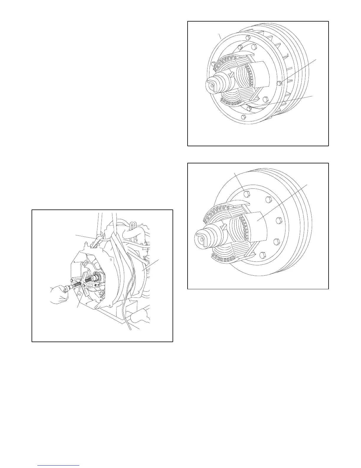
22. Mark the fans position on the rotor/drive disc
assembly with a permanent marker.
23. Remove the four screws with spacers and the four
screws without spacers. See Figure 9-7.
24. Remove the fan and fan spacers. See Figure 9-7.
25. Remove the eight bolts and remove the drive
disc/rotor assembly from the engine flywheel. See
Figure 9-8.
26. Clamp the rotor in a soft-jaw vise. Remove the eight
bolts and remove the drive disc assembly from the
rotor. SeeFigure9-9.
558867
2
1. Sling
2. Fan guard
3. Two-jaw puller
1
3
Figure 9-6 Stator Assembly Removal
558868
1
2
3
1. Fan
2. Screws with spacers (4)
3. Screws without spacers (4)
Figure 9-7 Fan Removal
558869
1. Bolts (8)
2. Rotor assembly
1
2
Figure 9-8 Disc/Rotor Assembly
 Loading...


