Disassembly/Reassembly 8-5TP-5606 6/02
1-932
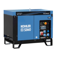
Figure 8-14. Removing the Drive Disk
Single-Phase Generator
Brushes
The brushes transfer current from the voltage regulator
to the slip rings. Since the brushes carry a low current,
they should last the life of the generator. Abrasive dust
on the slip rings could, however, shorten the life of the
brushes. Excessive arcing at the brushes could damage
the voltage regulator. Arcing could be caused by weak
springs, damaged slip rings, sticking brushes, loose
holder, or poor brush contact due to dirt.
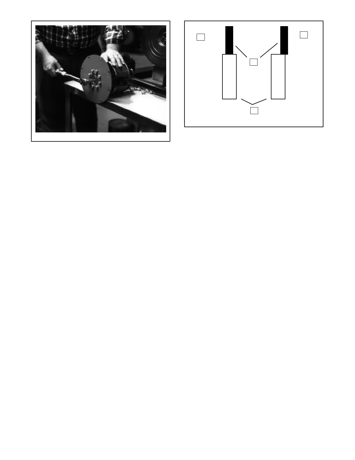
The brushes must be free to move within the holder and
be held in proper contact by the springs. When properly
positioned, spring pressure on the brush surface will
cause the brush to wear evenly. Brushes must ride
100% on the rings or arcing will occur and cause burned
rings or failure of the voltage regulator. Figure 8-15
shows the correct positioning of the brushes. Add or
remove shims as necessary to center brushes on slip
rings.
Replace brushes if they show excessive or uneven
wear.
TP-5340-7
1. Correct Positioning
2. Improper Positioning
3. Brushes
4. Generator Slip Rings
1
2
3
4
Figure 8-15. Brush Positioning
Single-Phase Generator
Slip Ring
If slip ring replacement is necessary, have the rotor
removed from the unit (follow the generator
disassembly procedure found in Section 8). Using a
soldering gun, heat the wires around the two terminal
ends of the slip ring. Carefully unravel the wires to
remove from each terminal. Pull off the slip ring using a
gear puller and clean the rotor shaft surface.
Replace the new slip ring (Kohler part number 238134)
onto the rotor shaft (with the terminal end pointing
outward) using a press with a proper size fixture.
Position slip ring onto the rotor shaft as far as the collar
permits. Exhibit care in routing the rotor leads through
the keyway (the lengthwise groove on the rotor shaft) so
as not to pinch or cut through insulation. Rewrap the
wires around each terminal on the slip ring and resolder.
See Figure 8-16. Mount the rotor onto a lathe and turn
the slip ring outer diameter to the dimension shown in
Figure 8-17 with a surface finish of 64 micro-inch.
 Loading...