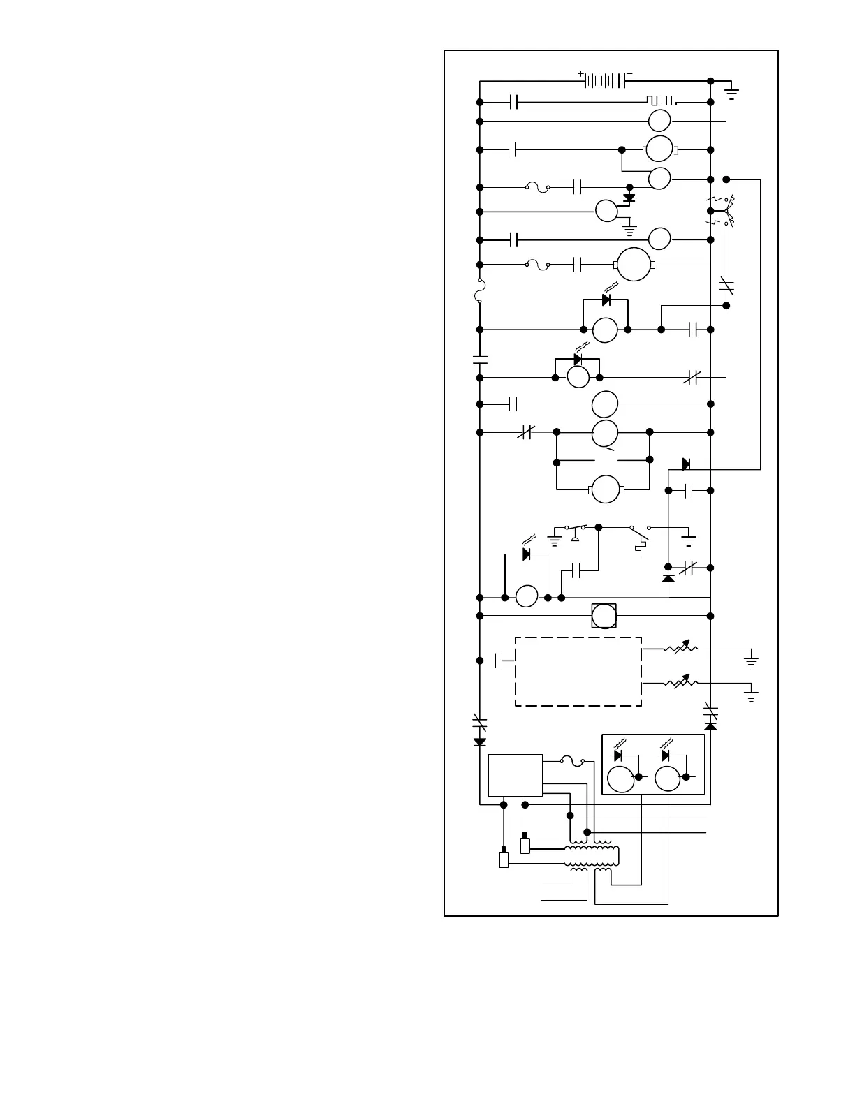
TP-5606 6/025-4 Controller Troubleshooting
Automatic Safety Shutdowns
The engine is equipped with two switches that monitor
critical operating conditions. These switches are:
D A High Engine Temperature Switch that closes
when engine coolant temperature rises toward an
unsafe level.
D A Low Oil Pressure Switch, which closes when the
oil pressure is insufficient, to indicate inadequate
lubrication of the engine.
During normal running, closing either of the above
switches results in an engine shutdown. During start-up,
this shutdown function is disabled by normally open
contacts of the K5 relay until 5 to 10 seconds after the
engine starts in order to allow the monitored conditions
to stabilize.
Once the normally open contacts of K5 close, the engine
safety switches are enabled. If either switch then closes,
the K4 relay is energized (LED4 lights). Energizing relay
K4 causes the normally open K4A contacts to close,
latching the K4 relay in an energized condition.
At the same time the K4A contacts close, the normally
closed K4B contacts open to de-energize the FP (fuel
pump) motor and the K25 relay. The normally open K25
contacts then open to de-energize the FS (fuel supply)
solenoid, turning off the flow of fuel. With the fuel supply
and fuel pump both turned off, the engine shuts off.
When the engine shuts off, the generator output decays
and causes relays K1 and K5 to de-energize (LED1 and
LED5 go out). The normally open K1D contacts then
open, de-energizing the K2 relay (LED2 goes out) and
opening the normally open K2 contacts to interrupt
power to the remaining controller relay circuits,
including relay K4. As a result, the latch-up of the K4
relay is broken to return the controller circuits to a normal
prestart condition.
K5
K4A
LED4
K4
K2
K1A
10 A.
MAIN FIELD
L2
LO
LO
L1
VOLTAGE
REGULATOR
LED1 LED5
K1 K5
12 VDC
AIR HEATER
C1
M
FS
S
10 A.
K25
K30
FP
10 A.
START
STOP/
PREHEAT
K1C
K1D
K1E
K2
K3
K3
K2
K20
S
B.C.
ALT
LED3
LED2
C1
15 A.
K30
12VDC
FAN
K25
K4B
K20
HR
REMOTE PANEL
K1F
K1B
START
LOW OIL
PRESS.
HIGH
ENGINE
TEMP.
Figure 5-4. Single-Phase Generator Sequence of
Operation, Emergency Shutdowns
 Loading...