7-6 Component Testing and Adjustment TP-5606 6/02
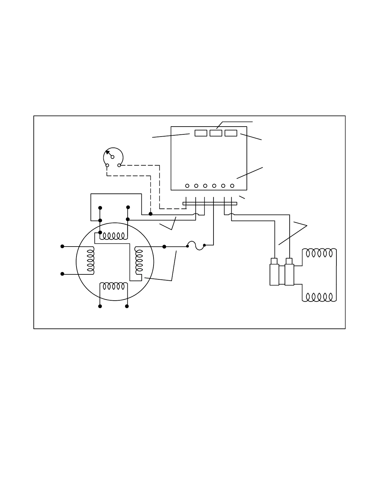
PowerBoostä IIIE Voltage
Regulator Adjustment
The voltage regulator is factory set for proper generator
operation under a variety of load conditions. Under
normal circumstances, no further adjustment is
necessary. However, if the regulator is replaced or has
been tampered with, readjust according to the following
procedure. Voltage regulator components are identified
in Figure 7-4 and described in the following paragraphs.
NOTE
The voltage regulator is located in the junction box.
Adjustments are possible without removing the
regulator from the junction box. See Figure 7-5.
+--
OPTIONAL
REMOTE
RHEOSTAT
(See NOTE A)
ROTOR
STATOR
VOLTAGE ADJUSTMENT POT
STABILIZER POT
VOLTS/HZ POT
SENSING
MAIN
MAIN
CONTROL
10 AMP
FUSE
DC
OUTPUT
AC POWER
INPUT (AUX.)
4
3
33
44
21
B1
B2
55
TP-5414-7
VOLTAGE
REGULATOR
POWERBOOST
IIIE
GY R Y O W BK
66 33 55 -- +
LEAD COLOR
STATOR/ROTOR
CONNECTIONS
(For reference
only)
66
33
44
Figure 7-4. PowerBoostä IIIE Voltage Regulator
 Loading...