7-18 Component Testing and Adjustment TP-5606 6/02
Rotor
The four-pole rotor creates the magnetic field needed to
sustain alternating current in the stator windings. Prior to
testing, inspect the rotor for visible damage to pole
shoes, insulation, exposed coil windings, and slip ring
surfaces. Check rotor bearing for noisy operation,
excessive wear, and heat discoloration. Replace or
repair these components if any of the above conditions
exist.
Single-Phase Rotor Tests
Slip rings acquire a glossy brown finish in normal
operation. Do not attempt to maintain a bright, newly
machined appearance. Ordinary cleaning with a dry,
lint-free cloth is usually sufficient. Very fine sandpaper
(#00) may be used to remove roughness. Use light
pressure on the sandpaper. Do not use emery or
carborundum paper or cloth. Clean out all carbon dust
from the generator. If the rings are black or pitted,
remove the rotor and remove some of the surface
material using a lathe.
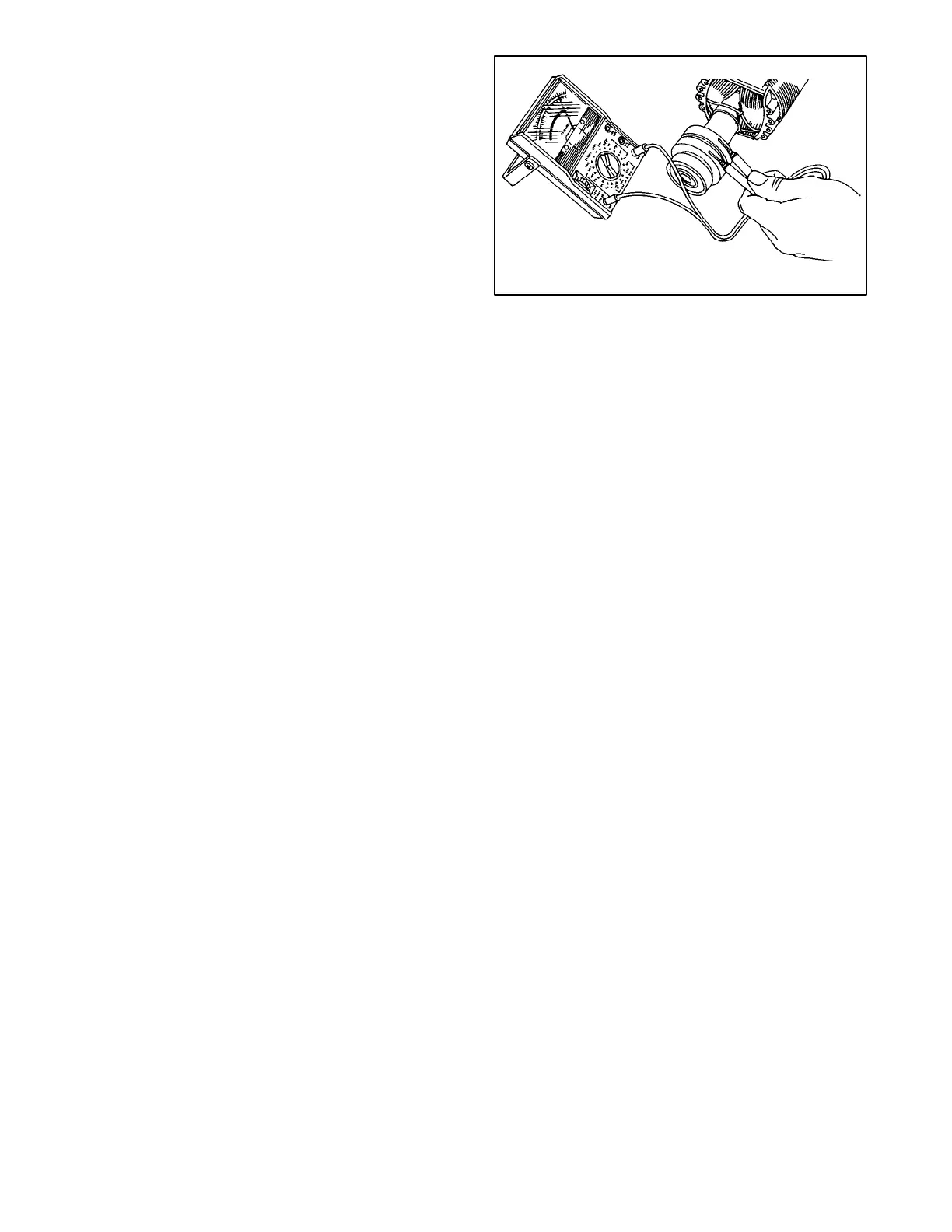
Check the rotor for continuity and resistance. Measure
the rotor resistance (ohms) between the two slip rings
(Figure 7-14). See Specifications--Generator in Section
1 for typical readings.
NOTE
Since ohmmeters do vary in their accuracy, use values
in Section 1 as a reference for approximate readings.
Readings must be at room temperature or about 70° F
(21° C). Rotor resistance will vary directly with increase
in temperature.
To check for rotor shorted to ground, adjust ohmmeter to
zero ohms. Touch one ohmmeter lead to either slip ring
and other lead to rotor poles or shaft. Meter should
register no continuity.
1-362
Figure 7-14. Rotor Resistance Check
NOTE
When checking rotor resistance with rotor installed,
brushes must not be in contact with rotor slip rings. Use
brush retainer on brushes for accurate resistance
readings.
The rotor must be repaired or replaced if any faults are
detected in the previous tests.
Three-Phase Rotor Tests
Check the rotor for continuity and resistance. To perform
check, disconnect rotor leads from rectifier module
circuit board and then measure the rotor resistance
(ohms) between the two rotor leads (Figure 7-15). See
Specifications--Generator in Section 1 for typical
readings.
NOTE
Since ohmmeters do vary in their accuracy, use values
in Section 1 as a reference for approximate readings.
Readings must be at room temperature or about 70° F
(21° C). Rotor resistance will vary directly with increase
in temperature.
 Loading...