TP-6073 4/0672 Section 10 Wiring Diagrams
10.12Four-Lead Reconnection
The following drawing illustrates the reconnection of
four-lead generator sets. In all cases, follow the
National Electrical Code (NEC) guidelines.
NOTICE
Voltage reconnection. Affix a notice to the generator set after
reconnecting the set to a voltage different from the voltage on
the nameplate. Order voltage reconnection decal 246242
from an authorized service distributor/dealer.
100-120 Volt Configurations
GRD.
L1
L2
4321
L0 (Neutral)
L0
Ground
Load
Side
Line
Side
Two-Pole
Circuit
Breaker
Jumper
lead
Figure 10-1 100-120 Volt, 3-Wire Configuration
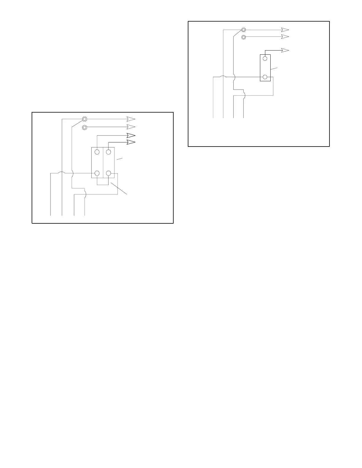
If the installation requires a factory two-pole circuit
breaker, do not connect the load-side terminals of the
circuit breaker together; see Figure 10-1. If the
installation requires a 100-120 volt, 2-wire system, use a
single-pole circuit breaker. See Figure 10-2. When
connecting stator phase leads together, size the output
lead (L1) to handle the amperage. Use a jumper lead on
the line side of the circuit breaker to balance the load of
the generator set.
4321
Stator Leads
L0
GRD.
L1
L0 (Neutral)
Line
Side
Single-Pole
Circuit
Breaker
Ground
Load
Side
60 Hz 50 Hz
L0-L1 100-120 Volt 100-120 Volt
L0-L2 100-120 Volt 100-120 Volt
Figure 10-2 100-120 Volt 2-Wire Configuration
100-120/200-240 Volt Configurations
The 100-120/200-240 volt configuration does not use a
jumper lead. If the unit was originally wired for straight
100-120 volt, 3 wire, remove the jumper lead (see
Figure 10-1 for location). Select a two-pole circuit
breaker. Application of two single-pole circuit breakers
does not conform to NEC requirements for supplying a
200-240 volt load—even if the breakers are
mechanically attached together. Leads L1 and L2 are
for different phases—never connect them together.
 Loading...


