TP-6735 7/1792 Section 6 Disassembly/Reassembly
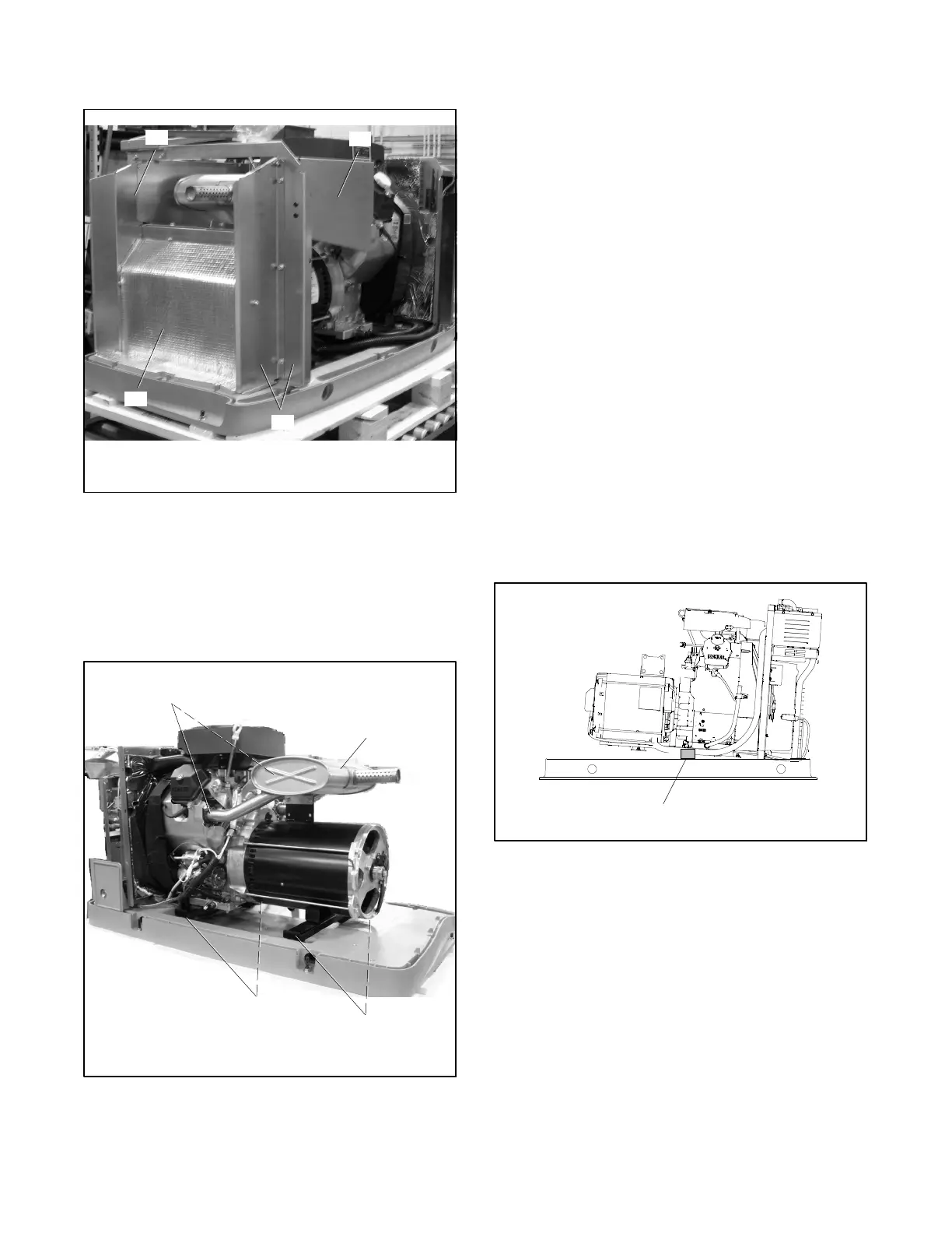
18. Remove the remaining exhaust duct panels and
alternator air inlet duct. See Figure 6-10.
2
TP-6735
1. Alternator duct
2. Exhaust duct panels
1
2
2
Figure 6-10 Exhaust and Alternator Ducts
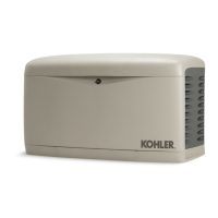
19. Disconnect the muffler from the engine at the two
flange connections and remove the muffler. See
Figure 6-11.
Note: Use new exhaust gaskets when re-installing
the muffler.
1. Exhaust flanges (qty. 2)
2. Muffler
3. Alternator vibromounts (qty. 2)
4. Engine vibromounts (qty. 2)
TP-6735
2
1
3
4
Figure 6-11 Muffler and Vibromounts
Generator Disassembly
20. Disconnect the following alternator wiring inside
the controller junction box. See the wiring
diagrams in Section 7.
a. Disconnect lead 55 from the mini-breaker on
the controller.
b. Disconnect P2 from the controller.
c. Disconnect leads 2 and 3 from neutral stud L0.
d. Disconnect leads 1 and 4 from the circuit
breaker.
21. Remove the bolts securing the two alternator end
vibromounts to the skid. Loosen the two engine
vibromounts. See Figure 6-11.
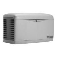
22. Raise the alternator end of the generator set
enough to place a wood support beneath the rear
of the engine. The wood support must be long
enough to span the opening in the base. See
Figure 6-12.
Note: Use a hoist or lifting device that is rated for
the weight of the generator set. See
Section 6.1.
GM51561
1
1. Engine support
Figure 6-12 Wood Support



 To Next Page