TP-6880 10/14 55Section 4 DC2 Controller Operation
4.2.3 LCD Display
The controller is equipped with a two-line x 16 character
backlit digital display with adjustable contrast. When the
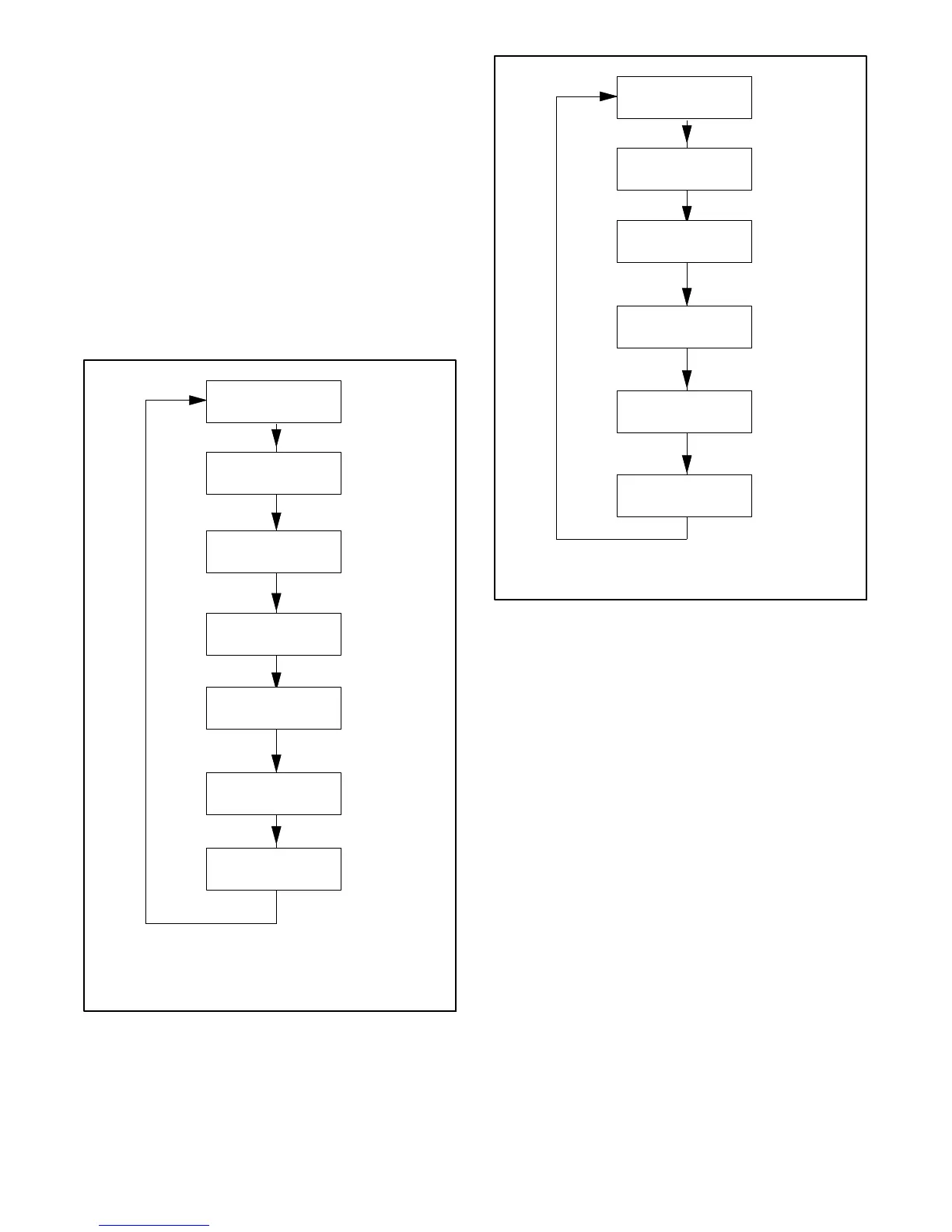
generator set is running, the messages shown in
Figure 4-5 are displayed. When the system is in AUTO,
the LCD display steps through the status messages
shown in Figure 4-6.
When a fault or warning condition exists, the controller
will show the corresponding message. See Section 2.5
for more information on fault and warning messages.
The display backlight turns off after about a minute of no
activity. The backlight turns on when a button is pressed
or when the generator set starts.
Running
ATS: Normal *
Voltage: 240V
Freq: 60.0Hz
Engine: 123F
Oil Pressure: OK
Battery 12.3V
Runtime: 12345.6 h
Next Exercise:
7d 6h 42m
Sample data shown.
Active Alert
(if any)
OnCue Status:
Disconnected [
* Model RXT ATS required
[ OnCue status is displayed only if OnCue password has
been reset.
Figure 4-5 Status Displays, Generator Running
Genset State
Standby
Battery 12.3V
Runtime: 12345.6 h
Next Exercise:
7d 6h 42m
Sample data shown.
Active Alert
(if any)
Next Maint:
123h or 12months
OnCue Status:
Disconnected
[ OnCue status is displayed only if OnCue password has
been reset.
Figure 4-6 Status Displays, Generator in Standby
4.3 Controller Power
The DC2 controller is powered by the generator set
engine starting battery.
Note: To disconnect controller power, disconnect the
utility power to the generator set and disconnect
the battery (negative lead first).
4.4 Battery Charging
The controller includes a built-in battery charger to
maintain the engine starting battery. The DC2 controller
monitors the battery voltage and provides a constant
14 ±2% VDC voltage and maximum 2.5 amps to
charge the battery.
The installer must connect 120 VAC/60Hz utility power
provided from the building on a breaker-protected circuit
for the built-in battery charger. See the Installation
Manual for instructions to connect power.
 Loading...


