18 TP-7091 4/23
1.4.2 Exhaust Requirements
Figure 5 gives the exhaust temperature at rated load. The engine exhaust mixes with the generator set cooling air at the exhaust
end of the enclosure. Mount the generator set so that the hot exhaust does not blow on plants or other combustible materials.
Maintain the clearances shown in the dimension drawing.
Figure 5 Exhaust Flow and Temperature
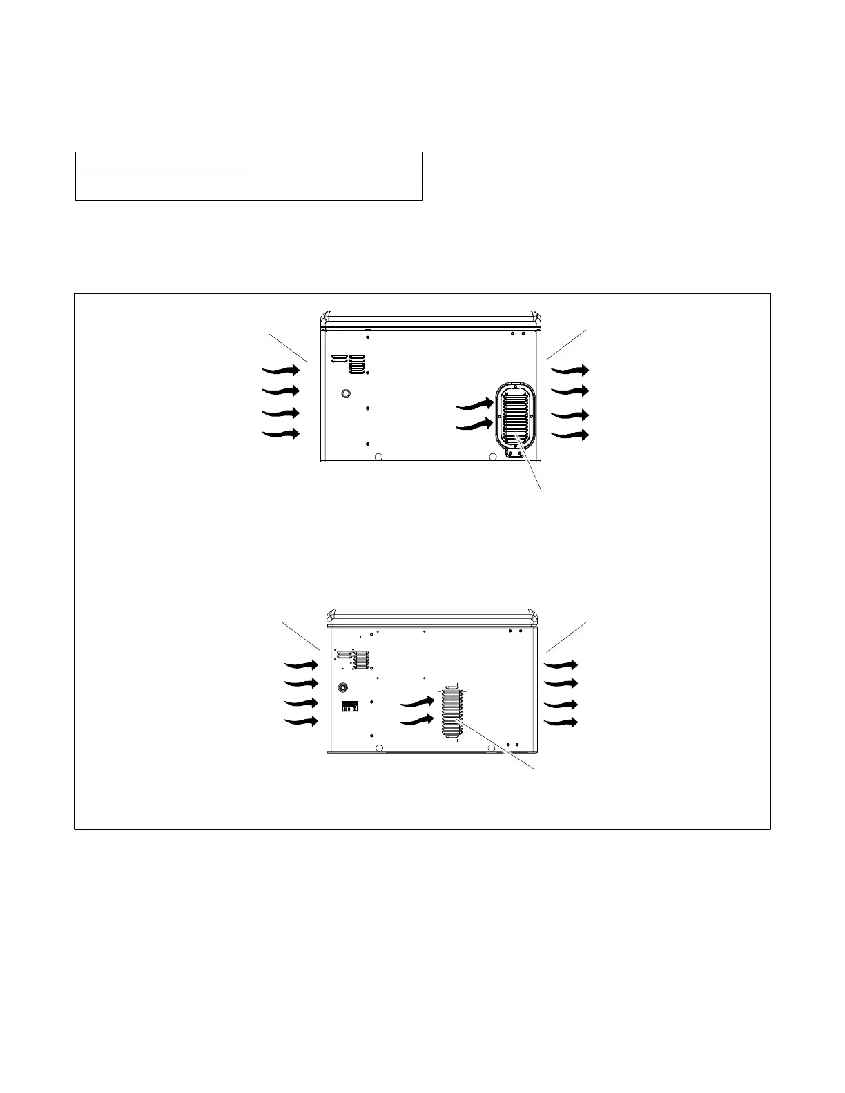
The generator set requires correct air flow for cooling and combustion. The inlet and outlet openings in the sound enclosure
provide the cooling and combustion air. Figure 6 shows the locations of the cooling air intake and exhaust vents. Inspect the air
inlet and outlet openings inside and outside the enclosure to ensure that the air flow is not blocked.
Figure 6 Cooling Air Intake and Exhaust
1.5 Dimension Drawings
See the dimension drawings in the Drawings and Diagrams section for the generator set dimensions, fuel and electric inlet
locations, and recommended clearance.
 Loading...
