TP-6862 6/14 21Section 4 Exhaust System
Waterline
7
14
13
12
15
10
9
8
19
11
20
6
17
4
5
22
16
23
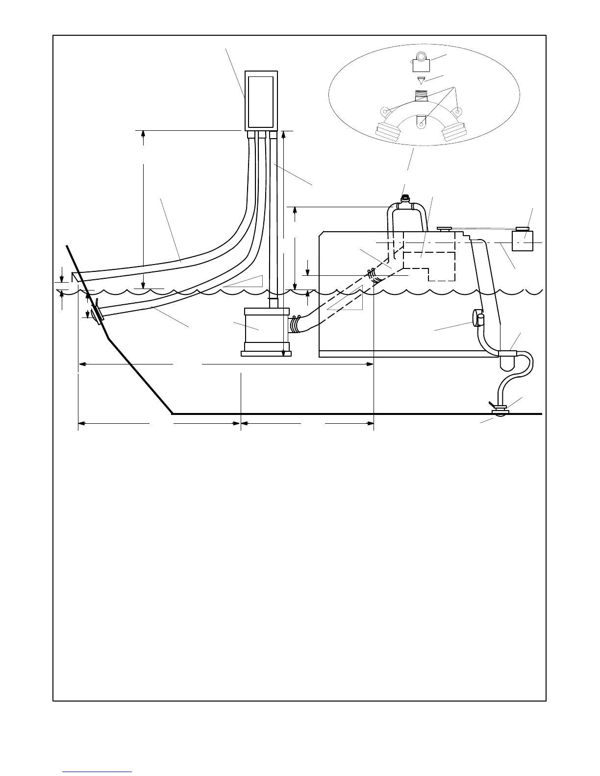
1. Cap
2. Reed valve
3. Mounting base
4. Maximum silencer vertical lift of 1.2 m (4 ft.)
5. Exhaust mixer elbow distance above waterline; if less than
23 cm (9 in.), a siphon break is required
6. Minimum siphon break distance above waterline of 30.5 cm
(1 ft.)
7. Siphon break
8. Exhaust m ixer elbow
9. Heat exchanger (locations vary by model)
10. Coolant recovery tank (located on the unit on some models)
11. Indicates the coolant recovery tank is at the same height as the
heat exchanger
12. Seawater strainer
13. Seacock
14. Intake strainer
15. Engine-driven seawater pump
16. Minimum exhaust hose pitch of 1.3 cm per 30.5 cm (0.5 in. per ft.)
17. Maximum distance between silencer and exhaust mixer elbow
of 3 m (10 ft.)
18. Maximum distance between silencer and exhaust outlet of
1.5 m (5 ft.)
19. Silencer (customer-supplied)
20. Minimum exhaust hose pitch of 1.3 cm per 30.5 cm
(0.5 in. per ft.)
21. Maximum distance between exhaust outlet and generator of
4.6 m (15 ft.)
22. Minimum exhaust outlet distance above waterline of 10 cm
(4 in.)
23. Exhaust hose, exhaust gas outlet hose after separator. See
Figure 4-1 for hose sizes.
24. Gas/water separator (optional). Install directly above the
canister muffler.
25. Distance above waterline for drain outlet from silencer must be
equal to or greater than water drain (item 26) to be greater
than 30.5 cm (1 ft.)
26. Wa ter drain distance below waterline
27. Water drain (separated water from item 24)
28. System installer is responsible for designing enough capacity
into the lift muffler and plumbing to prevent engine water
ingestion upon shutdown. Otherwise, water will drain back
into item 19 on generator set shutdown.
Note: Read the text for complete explanation of dimensions and
other installation considerations.
Note: Numbers in illustration refer to callouts below and not to
dimensions.
Note: Use two hose clamps on each end of all flexible exhaust
hose connections.
Note: Data applies to both rear- and side-exhaust installations.
Note: Damage caused by water ingestion will not be covered by
the generator warranty.
21
24
2
1
3
18
25
26
28
27
Figure 4-7 Typical Mid- and Below-Waterline Installation with Optional Gas/Water Separator
 Loading...