TP-6862 6/1426 Section 5 Fuel System
5.2 Fuel Lines
Return the generator set fuel return line to the fuel tank.
Locate the fuel return line as far as practical from the fuel
pickup to allow the tank fuel to cool the return fuel before
delivery back to the fuel injectors. Incoming fuel cools
the injectors to achieve maximum engine efficiency.
Note: Do not tee into the main propulsion engine’s fuel
line.
Under no circumstances should the propulsion engine
and generator set share pickup or return lines (through a
tee arrangement) that would allow the larger engine to
starve fuel from the smaller engine. It is possible that the
operation of either engine could completely drain the
fuel line of the other engine and make starting difficult.
Use a flexible hose section to connect the metallic line
from the fuel tank to the engine’s fuel pump inlet
connection point. Also, use a flexible hose section to
connect the metallic line from the fuel tank to the fuel
return connection point. The flexible section allows
vibrational motion of the generator set during operation.
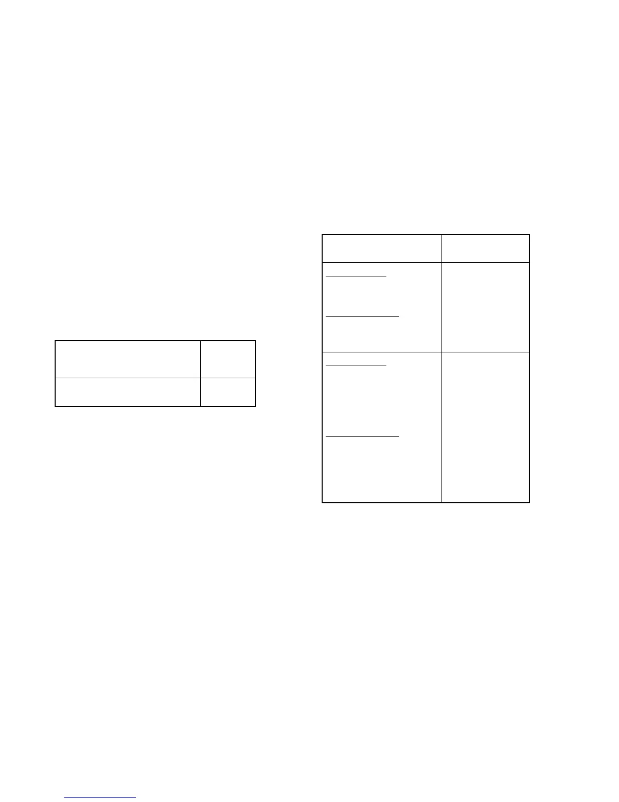
Model
Fuel Line
ID Size
mm (in.)
40--150EOZDJ/EOZCJ
40--125EFOZDJ/EFOCJ
9.7 (3/8)
Figure 5-2 Fuel Line ID Size
See Figure 5-2 for the ID size of the customer-supplied
fuel line that connects to the fuel pump and fuel return.
Route the fuel lines from the fuel tank in a gradual incline
to the engine. Do not exceed the height of the generator
set and do not route fuel lines above the generator set.
Comply with USCG regulation 46CFR182.20 regarding
fuel lines and supports.
See Section 7 for fuel feed pump inlet connection and
fuel return line connection.
5.3 Fuel Filters
Conform to USCG regulations regarding inline fuel
filters or strainers.
5.4 Fuel/Water Separator
A fuel/water separator is standard on 33--150 kW
models. Consult the engine operation manual for
service procedure.
5.5 Fuel Pump Lift
See Figure 5-3 for fuel pump lift capabilities.
Model
Fuel Pump Lift
m (ft.)
Pleasure Craft:
40EOZDJ/33EFOZDJ
40EFOZDJ
50EFOZDJ
Commercial Craft:
40EOZCJ/33EFOZCJ
40EFOZCJ
50EFOZCJ
3 (10)
Pleasure Craft:
55EOZDJ/45EFOZDJ
65EOZDJ/55EFOZDJ
80EOZDJ/70EFOZDJ
99EOZDJ/80EFOZDJ
125EOZDJ/100EFOZDJ
150EOZDJ/125EFOZDJ
Commercial Craft:
55EOZCJ/45EFOZCJ
65EOZCJ/55EFOZCJ
80EOZCJ/70EFOZCJ
99EOZCJ/80EFOZCJ
125EOZCJ/100EFOZCJ
150EOZCJ/125EFOZCJ
2.4 (7.9)
Figure 5-3 Fuel Pump Lift
5.6 Fuel Consumption
Consult the current generator set specification sheets
for generator set fuel consumption rates.
 Loading...