TP-6862 6/1424 Section 4 Exhaust System
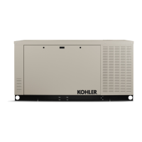
Satisfactory generator set performance requires proper
exhaust system installation. Figure 4-10 and
Figure 4-11 show typical arrangements for commercial
marine exhaust systems.
1
3
2
4
5
6
7
8
TP-5700-5
1. Supports
2. Pitch line downward
3. Silencer
4. Water trap
5. Drain petcock
6. Flexible section
7. Solid section 152--203 mm (6--8 in.)
8. Manifold
NOTE: Horizontal
silencer shown.
Figure 4-10 Exhaust System, End Inlet Silencer
2
6
5
1
8
7
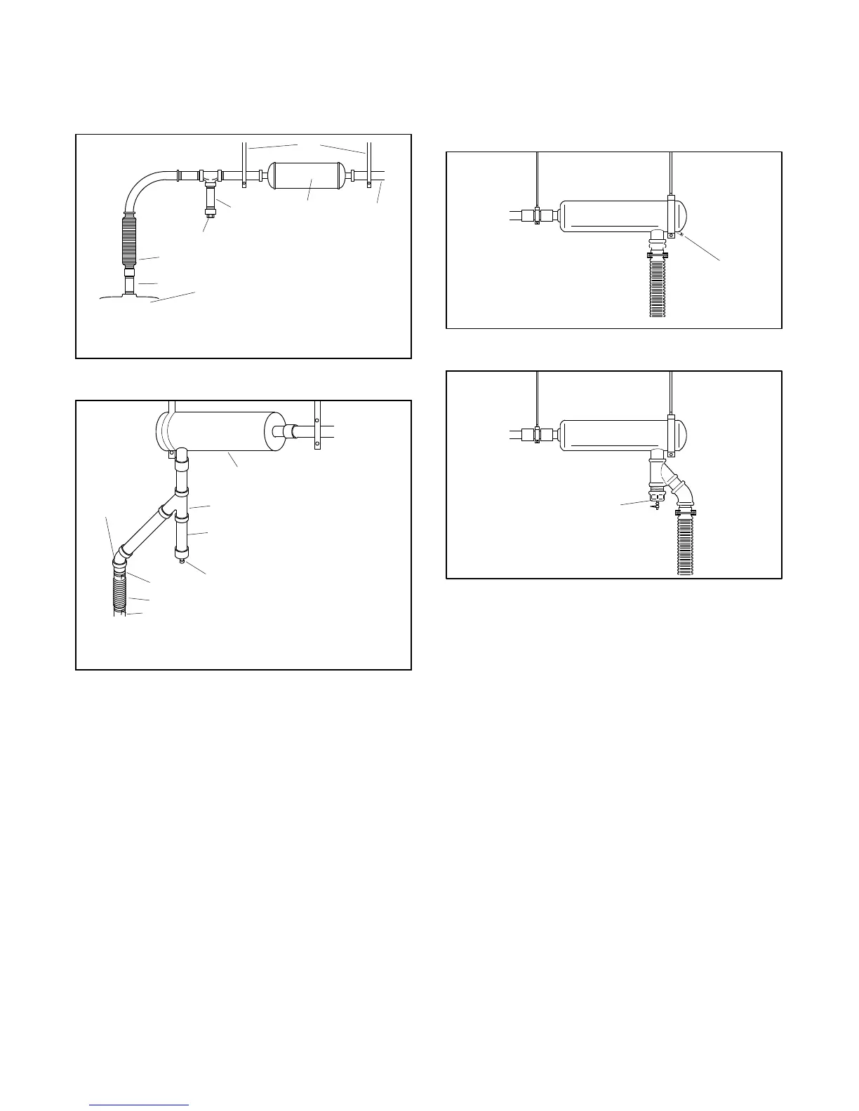
1. Silencer
2. 45 Y fitting
3. Water trap
4. Drain petcock
3
4
5. Outer diameter adapter and clamp
6. Flexible section
7. Manifold
8. 45 elbow
NOTE: Horizontal
silencer shown.
Figure 4-11 Exhaust System, Side Inlet Silencer
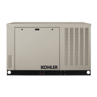
Ensure that there is a means to periodically drain
condensation in exhaust, such as a silencer equipped
with a drain plug (see Figure 4-12), or a wye- or tee-type
condensation trap with a drain plug, or petcock installed
between the engine and silencer (see Figure 4-13).
1
TP-5700-5
1. Pipe Plug
NOTE: Horizontal
silencer shown.
Figure 4-12 Silencer Condensation Drain Plug
1
TP-5700-5
1. Condensation t rap
NOTE: Horizontal
silencer shown.
Figure 4-13 Condensation Trap
 Loading...