6-24 Installation TP-5393 9/93
AC Load Lead Connections
Each set has four color-coded load leads and a
connector for attaching flexible conduit from the
generator end bracket to the load terminal junctionbox
typically installed in the compartment. The black leads
(L1 and L2) are hot, the white lead (L0) is neutral, and
the green lead is the hazard ground.
NOTE
Route load leads through flexible conduit and keep
circuit awayfromthegenerator set, specificallyfueland
exhaust system components.
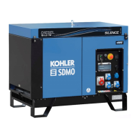
Figure 6-25 represents position and dimensions for
typicaljunctionboxinstallation.Ajunctionboxshouldbe
installed to make it accessible for inspection and
service.
Suggested Minimum Dimensions
1
2
2
1. Box for fieldconnection should be accessibleafter installationfor
inspection and servicing
2. 2” (50.8 mm)
Figure 6-25. RV Junction Box
TheACloadleadL0(white)isalwaystheneutralleadon
Kohlergeneratorsets—makesuretheneutralof theAC
circuit in the vehicle is connected to lead L0 (white). If
equipment ground-type plugs and receptacles (3
pronged)areusedinthevehicle,thegreenwiremustbe
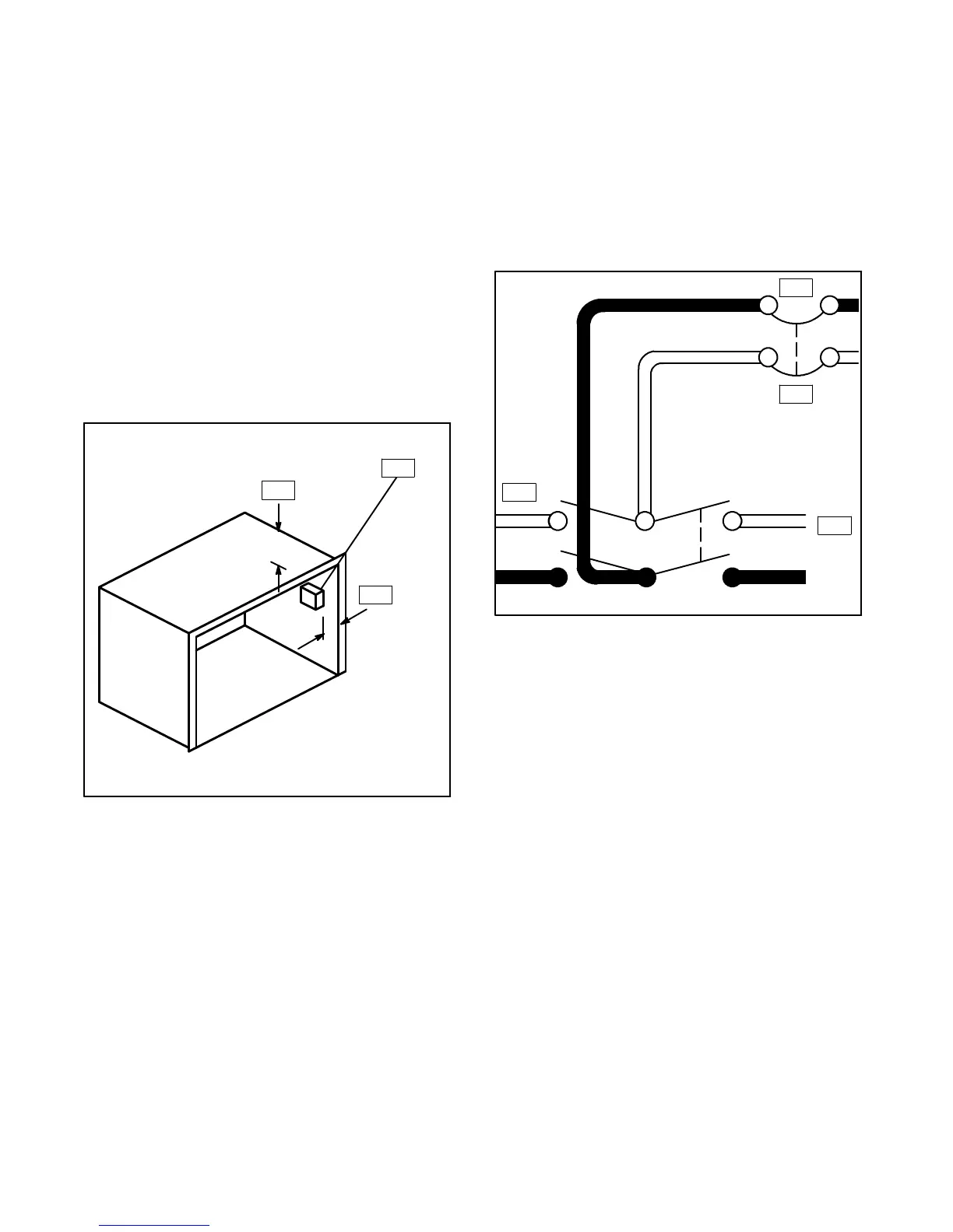
connected to the U-shaped pin. On vehicles whichalso
have provisions for using an outside AC power source,
the neutral as well as the hot (black) leads must be
completely isolated from the generator set when power
is switched to the out-side source. See Figure 6-26.
NN
N
L0
L1
1
2
3
4
1. AC vehicle circuit
2. Ground fault circuit protection
3. Generator set
4. 120-V outside power
Figure 6-26. Transfer Switch Connections 2-Wire
AC Circuit
NOTE
A double-pole, double-throw transfer switch rated for
the calculated load of the RV must be used to transfer
the load from one source to the other. A ground-fault
circuit interrupter should be installed in the wiring
system to protect all branch circuits.