6-6 Installation TP-5393 9/93
Air Requirements
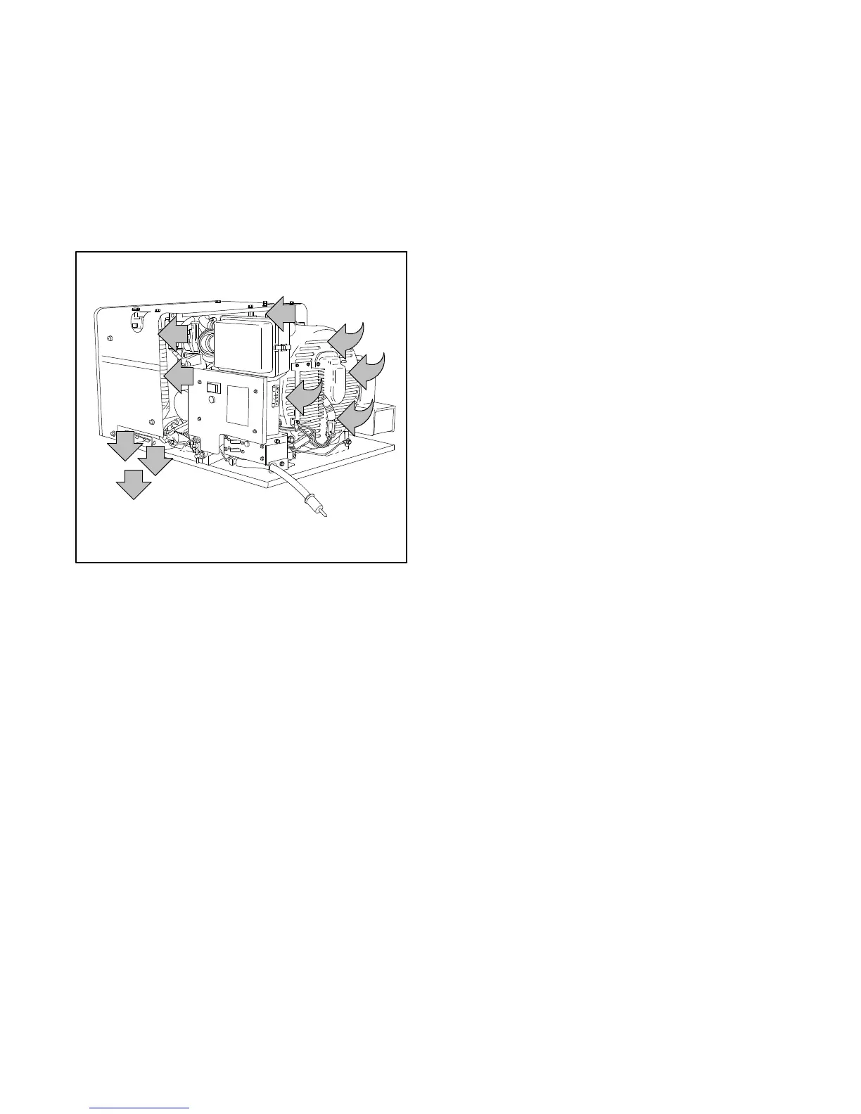
A fan on the rotor of the generator draws cooling air into
the compartment through the generator cooling slots
and expels it at the engine-generator adapter. The
engine of the generator set features an Air-Vact
reverse flow cooling system. Fins on the engine flywheel
pull cooling air past the fins of the cylinder heads and the
heated air is discharged downward and out of the
compartment through the discharge chute. See
Figure 6-7.
1-904
Figure 6-7. Cooling Air Circulation
Topreventdamagetothegeneratorset fromoverheating,
makesurethecompartmentopeningsarelargeenoughto
allow adequate circulation or cooling air. The minimum
free-air opening in the compartment is 85 sq. in. (548 sq.
cm.). The free-air opening may be located in the
compartment door, floor, or end wall. See Figure 6-8 for
positionof thefreeairopeningin thecompartment flooror
end wall. Position of the compartment door free-air
opening is shown in Figure6-9.
If the air-intake opening is located in the compartment
floor or end wall, a space must remain between the
generator end and the compartment air opening. The
width of the space must be equal to a point on the
compartment floor 5° from the top of the generator.
(Typically, a distance of 1.22 in. on most 4 and 5 kW
generatorinstallations.)SeeFigure 6-8.Afireprooffloor
(flooringmadeofanon-combustiblematerial)mustalso
be installed between the mounting tray and enclosure
walls. These precautions are necessary to prevent hot
airfromleavingthe generatorcompartment andigniting
combustible material beneath the coach.
NOTE
Installation of a baffle beneath theengine air discharge
is recommended to prevent expelled air from raising
dust or ruining grass beneath the coach.
 Loading...


