TP-5393 9/93 Installation 6-7
1
1
2
3
4
5
6
7
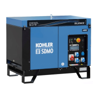
1. Generator end
2. 5°
3. End wall
4. Air inlet at floor or end wall
5. 1.22 in.
6. Compartment floor
7. Mounting tray must not cover any portion of air inlet/outlet
openings.
Figure 6-8. Floor or End Wall Air Inlets
1
2
3
4
5
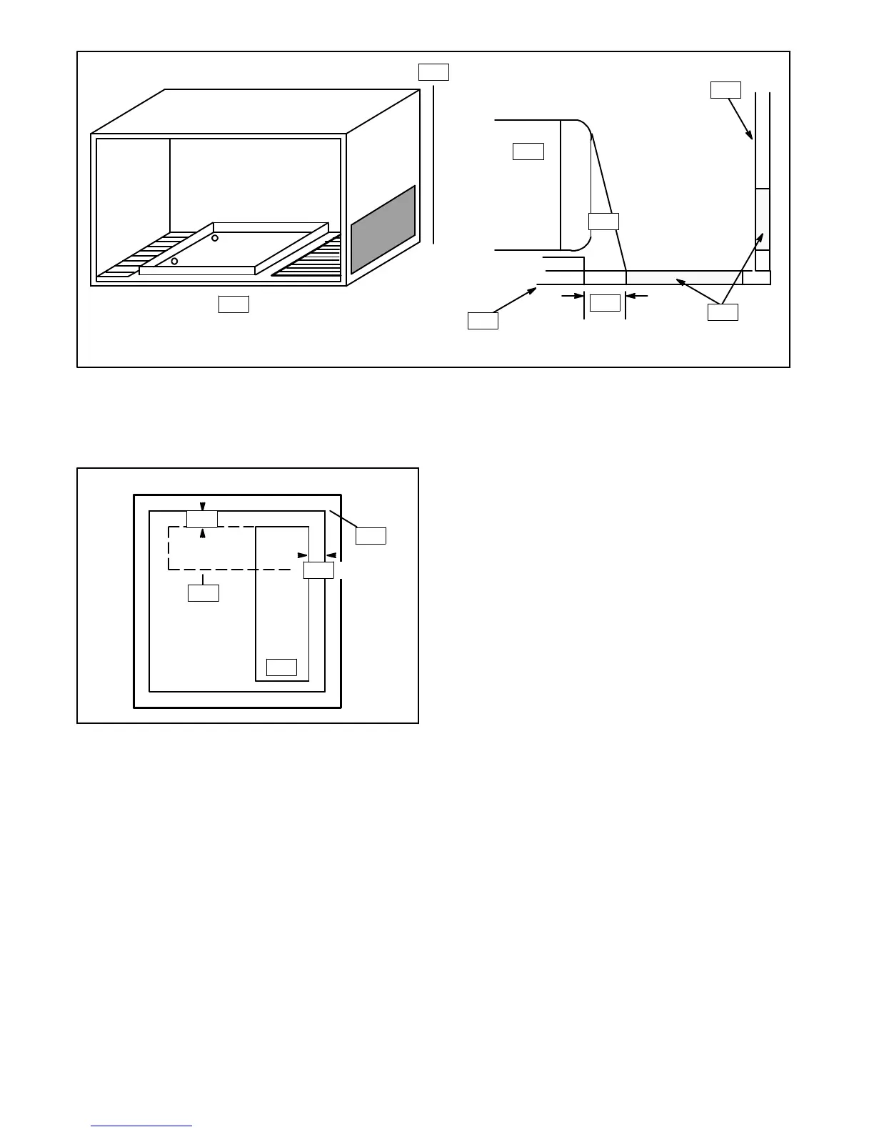
1. 3” minimum (76.2 mm)
2. 2” minimum (50.8 mm)
3. Generator end
4. Air in
5. (Optional)
Figure 6-9. Screen Position for
Compartment Door
Remember, louvers, screens, and
protective-decorative grill work definitely restrict the
effective air flow. Even a simple, relatively open mesh
screen as seen in Figure 6-10 will restrict air flow as
much as 45%. The intake opening must be increased to
compensate for such restrictions.