TP-5985 10/02 1Section 1 Service Views
Section 1 Service Views
7
4
20
27
26
23
24
30
6
29
10
9
14
22
8
16
11
13
21
25
18
ADV-6395-A
GY-250000-A
17
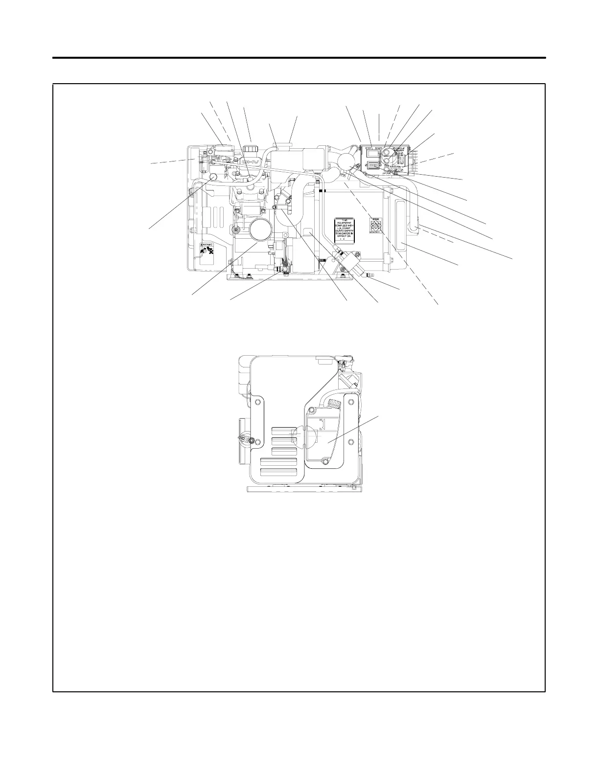
SERVICE VIEW
ENGINE-END VIEW
1
28
3
5
12
15
2
19
1. Electric choke (on carburetor)
2. Carburetor/choke linkage
3. Spark plugs (also one on nonservice side)
4. Oil fill
5. Overflow tube
6. Pressure cap (coolant fill location after draining coolant)
7. Controller
8. Start/Stop switch
9. Nameplate (top)
10. AC load lead connector (nonservice side)
11. Input fuse
12. Battery charging fuse
13. AC circuit breaker
14. Remote start connector (nonservice side)
15. Voltage regulator fuse
16. Hourmeter
17. Heat exchanger
18. Anticorrosion zinc anode
19. Seawater drain (remove plate)
20. Seawater pump (water inlet)
21. Cooling air inlet
22. Mixing elbow, water outlet/exhaust outlet (nonservice side)
23. Fuel feed pump (fuel inlet)
24. Oil check
25. Coolant drain (remove hose clamp to drain coolant)
26. Oil drain valve
27. Lube oil filter
28. Antidieseling solenoid (on carburetor)
29. Air intake silencer/backfire flame arrestor
30. Coolant overflow bottle (daily coolant check/fill location)
Note: Consult installation drawings in Spec Sheet or Installation
Manual for fuel- and battery-connection points.
Note: Consult distributor/dealer or Service Manual for items
not shown.
Figure 1-1 Service Views
 Loading...