TP-5985 10/02 17Section 3 Scheduled Maintenance
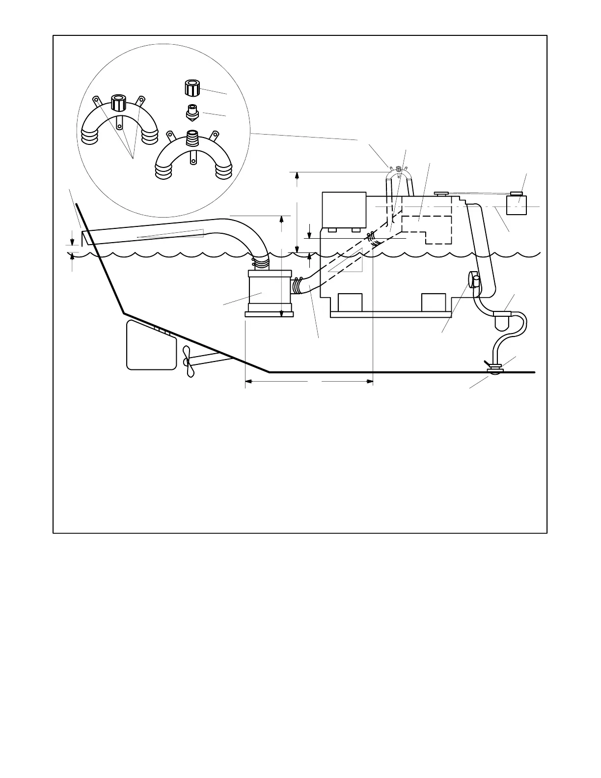
Waterline
1
2
3
7
8
9
19
10
11
12
13
14
15
16
17
18
21
20
6
5
4
TP-5586-3
22
1. Mounting base
2. Retaining cap
3. Reed valve assembly
4. Silencer vertical lift 1.2 m (4 ft.) max.
5. Exhaust mixer elbow distance above waterline. If less than
23 cm (9 in.), siphon break is required.
6. Siphon break distance above waterline 30.5 cm (1 ft.) min.
7. Siphon break
8. Exhaust mixer elbow
9. Heat exchanger (locations vary by model)
10. Coolant recovery tank
11. Locate coolant recovery tank at same height as heat exchanger
12. Seawater strainer
13. Seacock
14. Intake strainer
15. Engine-driven seawater pump
16. Exhaust hose pitch 1.3 cm per 30.5 cm (0.5 in. per ft.) min.
17. Water lock (optional)
18. Silencer distance from exhaust mixer elbow 3 m (10 ft.) max.
19. Silencer (customer-supplied)
20. Exhaust hose pitch 1.3 cm per 30.5 cm (0.5 in. per ft.) min.
21. Exhaust outlet distance above waterline 10 cm (4 in.) min.
22. Seawater outlet
Figure 3-9 Siphon Break (Plastic “U” Type) Installation
Note: Consult the installation manual for complete
explanation of dimensions and other installation
considerations.
 Loading...