TP-6137 5/0366 Section 10 Generator and Engine Disassembly/Reassembly
Figure 10-33 Protective Tube
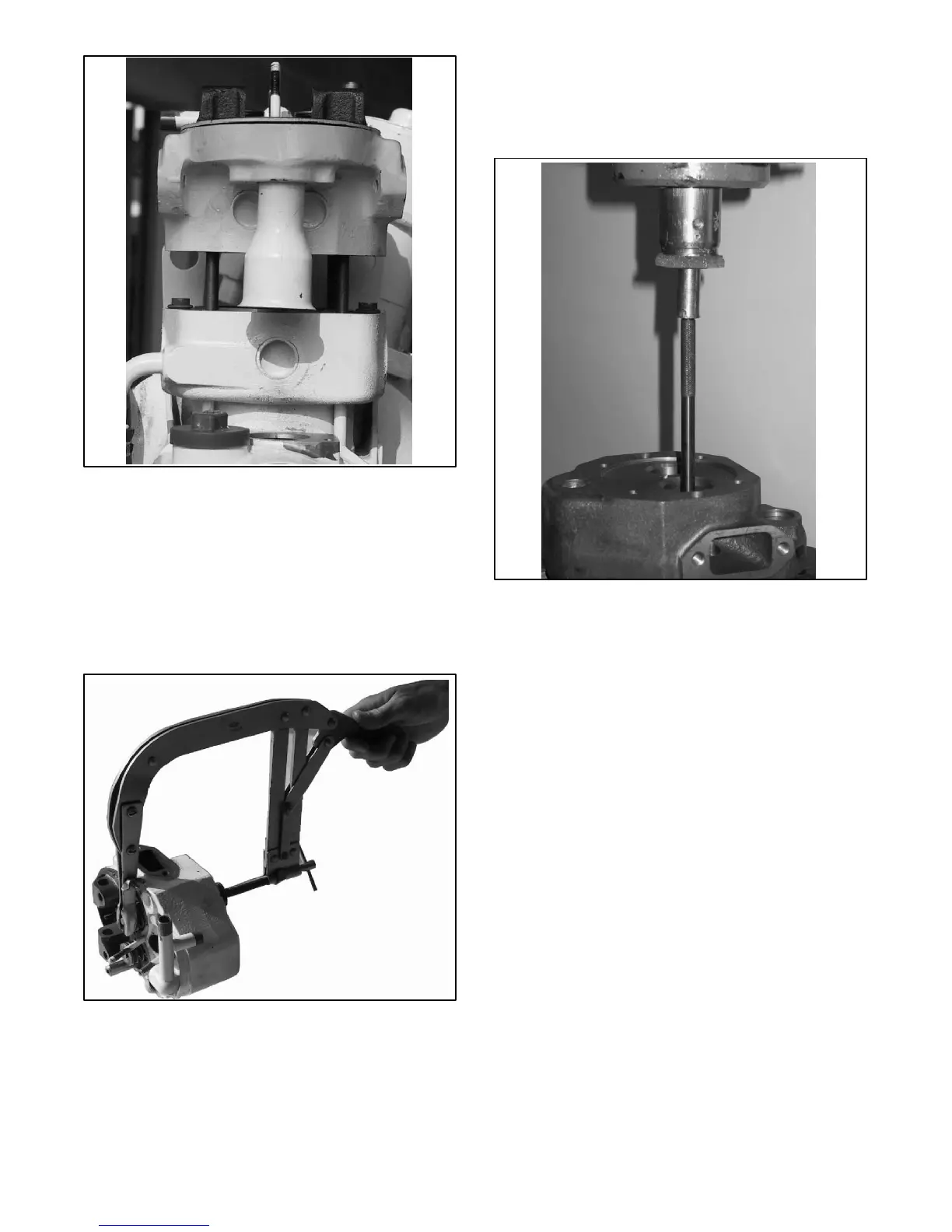
Disassembly the valves
1. Use the special tool shown in Figure 10-34 to
disassemble the valves. Consult the engine
service manual.
Note: Be aware of the two thin steel washers located
under the intake valve spring.
Figure 10-34 Valve
Replacing the valve guides
1. If valve guide replacement is necessary, use the
proper driver and press out the old guides from the
head. See Figure 10-35.
Figure 10-35 Valve Guide
Replacing the seats
The cylinder head is equipped with two valve ring seats
of wear-resistant steel. Consult the engine service
manual and the following procedure if the head seats
are so worn that a grinding valve rework will not ensure a
good gas proof. Use a valve seat cutter if a surface
rework is needed.
1. Insert the guide pin into the valve guide.
2. Rotate the cutting surface of the T-handled tool
applying light pressure to touch the ring seat. See
Figure 10-36.
Note: Do not cut too deep or use grinding compound.
Observe the allowable valve recess.
To check the sealing valves:
1. Put the sealing valves in their guides.
2. Install the springs and fill the intake/exhaust
openings on the head with a small amount of diesel
fuel oil.
3. A good valve seal occurs when the diesel fuel oil
leaks about 2 drops per minute.